Modeling a simple example
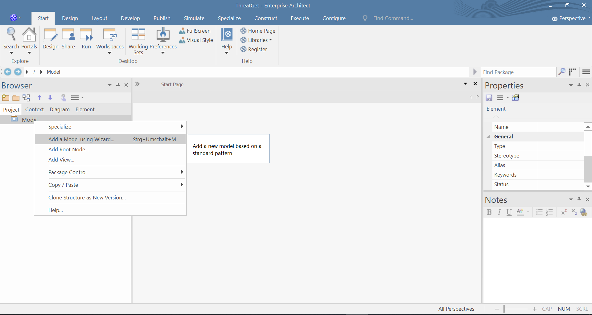
To start your model, first, create an empty ThreatGet diagram, this can be done by right clicking the Model from the Project Browser, and then clicking on Add a Model using Wizard, as shown below.
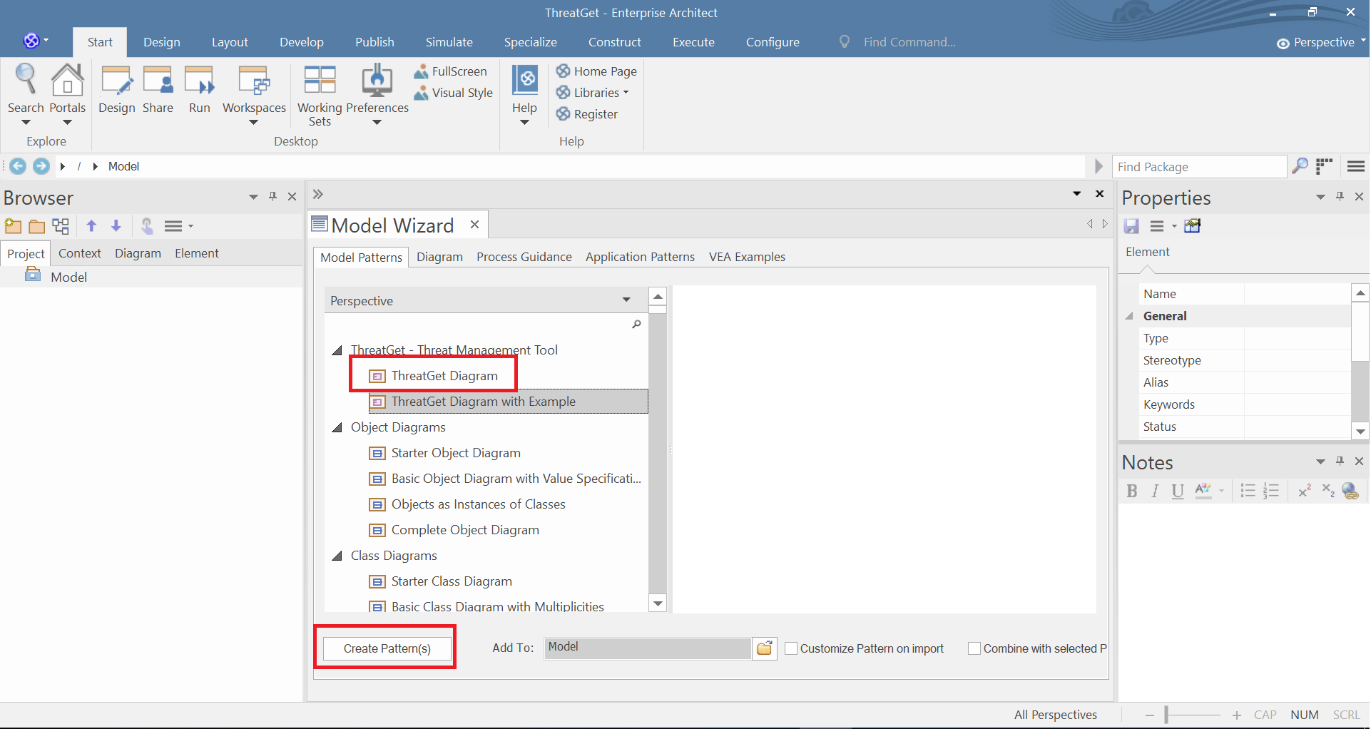
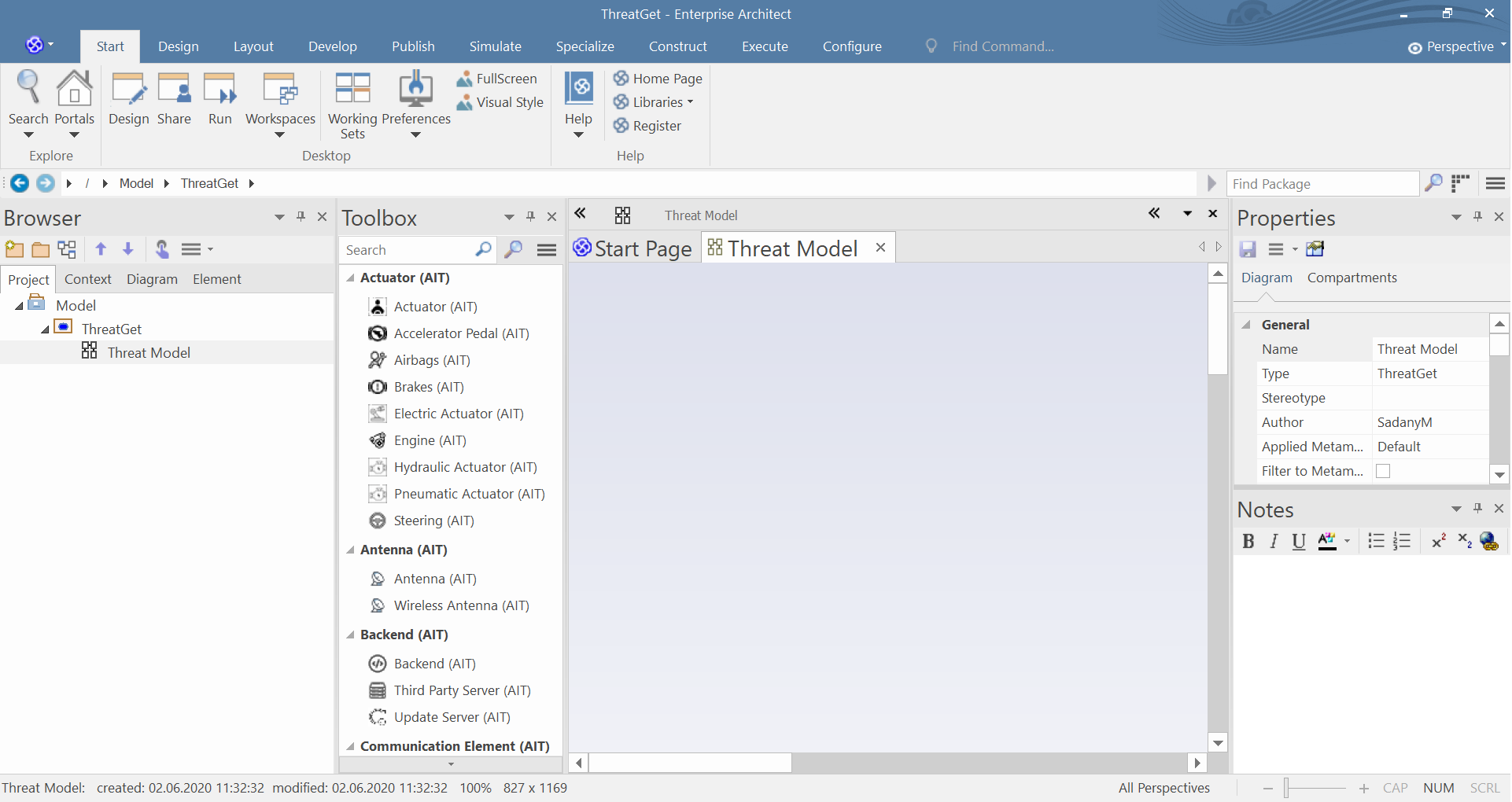
Select ThreatGet Diagramm from the model menu and click on Create Pattern(s) to create the diagram. The ThreatGet Toolbox is automatically selected after pressing Create Pattern.
The standard ThreatGet toolbox has elements of different categories as well as connections and boundaries. After each element we can see the creater of the element, in our case, the (AIT) is the creator of the predefined elements.
In the next steps we will model a model which represents a realistic example. We will model the interaction which appears when we open a car by using a distance key. So, it will handle the communication between a key fob and a car.
The purpose of the communication is to lock and unlock the vehicle. The key fob communicates via an antenna with a lock / unlock control unit. The signal is received via the antenna and passed on to the central control unit. The received signal is processed, then the feedback is sent to the users (e.g., the sight lights go on and off). The central control unit is connected to the infotainment system. The infotainment contains an integrated USB port. Both ECU's are communicating internally.
We need the following elements for modeling:
- Key Fob (AIT) from the Key Fob category
- Vehicle (AIT) from the External Interaction category
- High-performance ECU (AIT) from Electronic Control Unit category
- Communication ECU (AIT) from the Electronic Control Unit category
- Infotainment from (AIT) the Electronic Control Unit category
- USB (AIT) from the Interface category
Note: All connections are selected as Communication Flow from the Communication Flow category to simplify modeling.
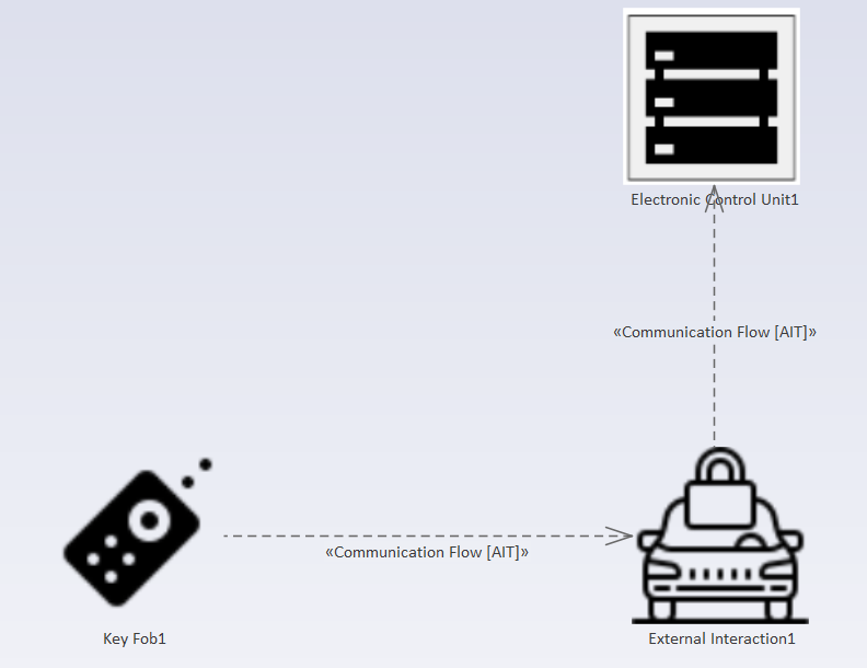
Create the key fob, vehicle, and high-performance ECU from the ThreatGet ToolBox by drag and drop. Create the connections by selecting Communication Flow from the Toolbox. Then click on the source element and keep the mouse button pressed and release the button over the target element.
Now double-click on an element to access the element properties. In our case, we change the properties of the vehicle. In the first step, we change the name to lock/unlock antenna.
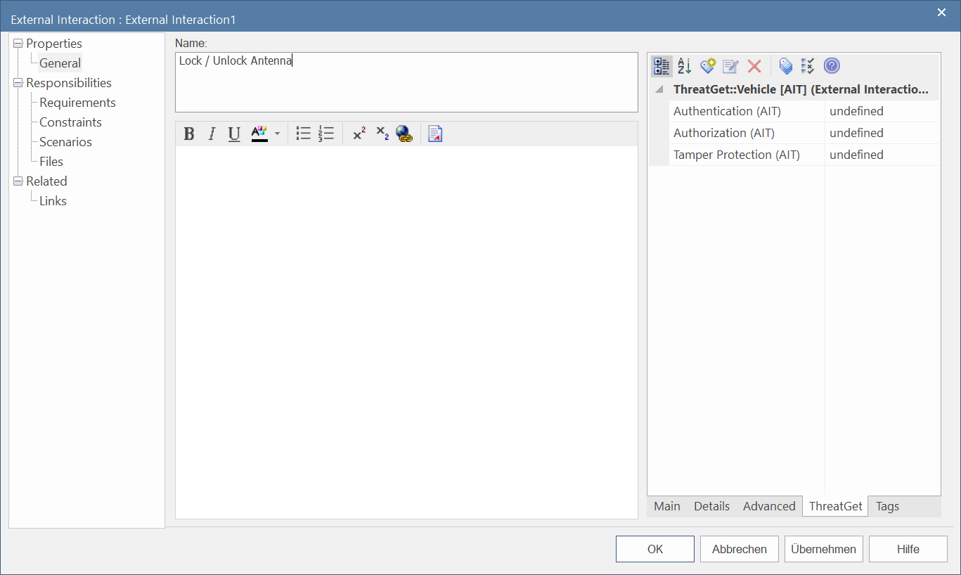
The properties also include ThreatGet Tagged Values. These are properties that were created by the Server Administrator. The creator of tag value is shown after the name of the property in parenthesis. In our case we can see that the (AIT) is the creator of the tagged value.
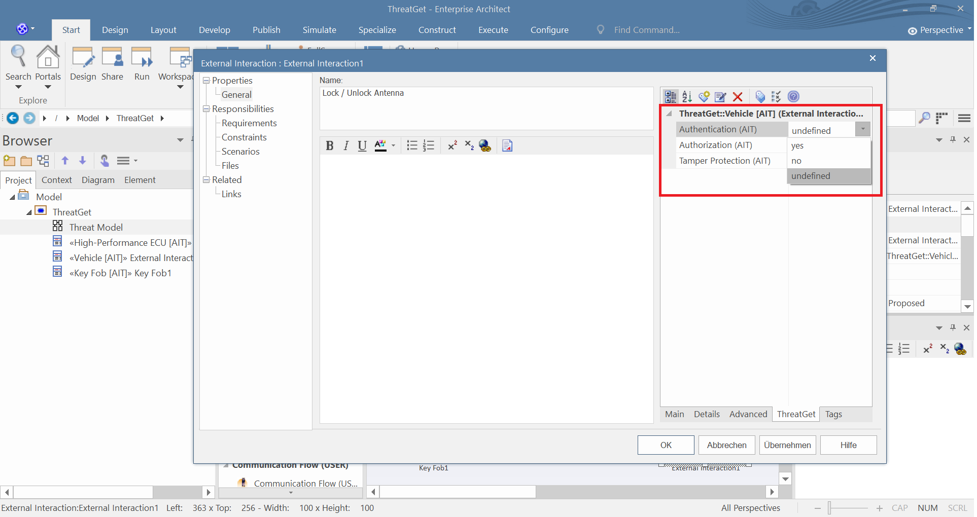
It is possible to change the values. You can always change one of the values from the dropdown menu. To create your own Tag Value, please have a look at Managing Tagged Values.
We now create the elements mentioned above, step by step, and then connect them with the connections. Your model should look like the diagram below.
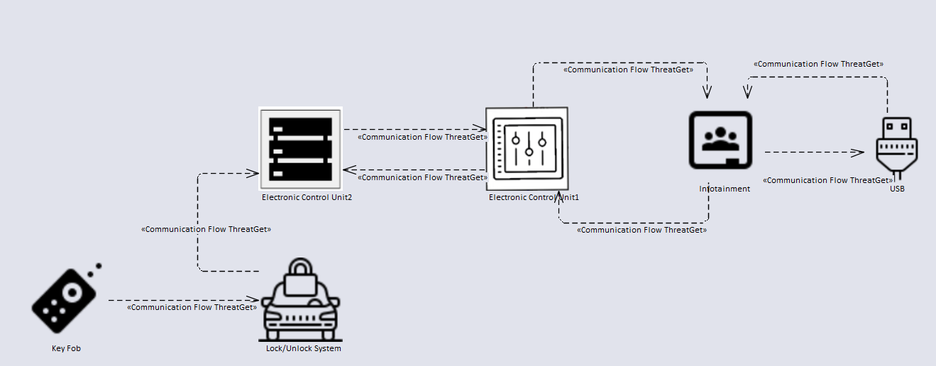
We are now ready to perform a threat analysis on this example.