THREATGET Rules
Introduction
Typically, threat modelling is based on two components. The first component is called the System Model. The system model contains an abstract representation of the system under consideration.
The second component is the so-called Threat Model. The threat model represents a knowledge base of known vulnerabilities, threats, threat scenarios, including their exploitation techniques and methods.
The principle of THREATGET is based on the automatic comparison of these two models. The system model is created by the user within the Enterprise Architect plugin. For this purpose, the user defines the Elements, Assets, Connectors, Interfaces and Boundaries in the web-based interface that can be used during the definition of it. Elements, assets, connectors, interfaces and boundaries are also referred to as diagram components.
Diagram components are largely described by their properties. These properties are also defined in the web-based interface and assigned to the components. The properties are called Tagged Values within the THREATGET plugin.
Note: The Boundary is the only diagram component for which no properties can be assigned.
Full Formal Syntax and Semantics Definition
As part of this documentation we developed a fully formal syntax and semantics for the THREATGET analysis language. It can be downloaded here
Use Case Example based on ISO/SAE 21434
In order to adequately represent the syntax and semantics of the analysis language, we present a use case example that originates from the automotive domain. The presented example was derived from the security standard ISO/SAE DIS 21434 "Road vehicles - Cybersecurity engineering" from February 2020 Annex G.
A modern vehicle contains a complex electronic infrastructure. Most cars have a full infotainment system and additional driving assistants as standard equipment. In addition to the necessary electronic control units (ECU), vehicles include an increasing number of externally accessible interfaces such as Bluetooth, WIFI, and Cellular communication. Due to the trend towards autonomous driving, vehicle-to-vehicle communication is also indispensable and offers further potential vulnerabilities that an attacker could exploit. Improving the security of a vehicle is an essential influencing factor for its overall safety and that of its occupants.
System Model
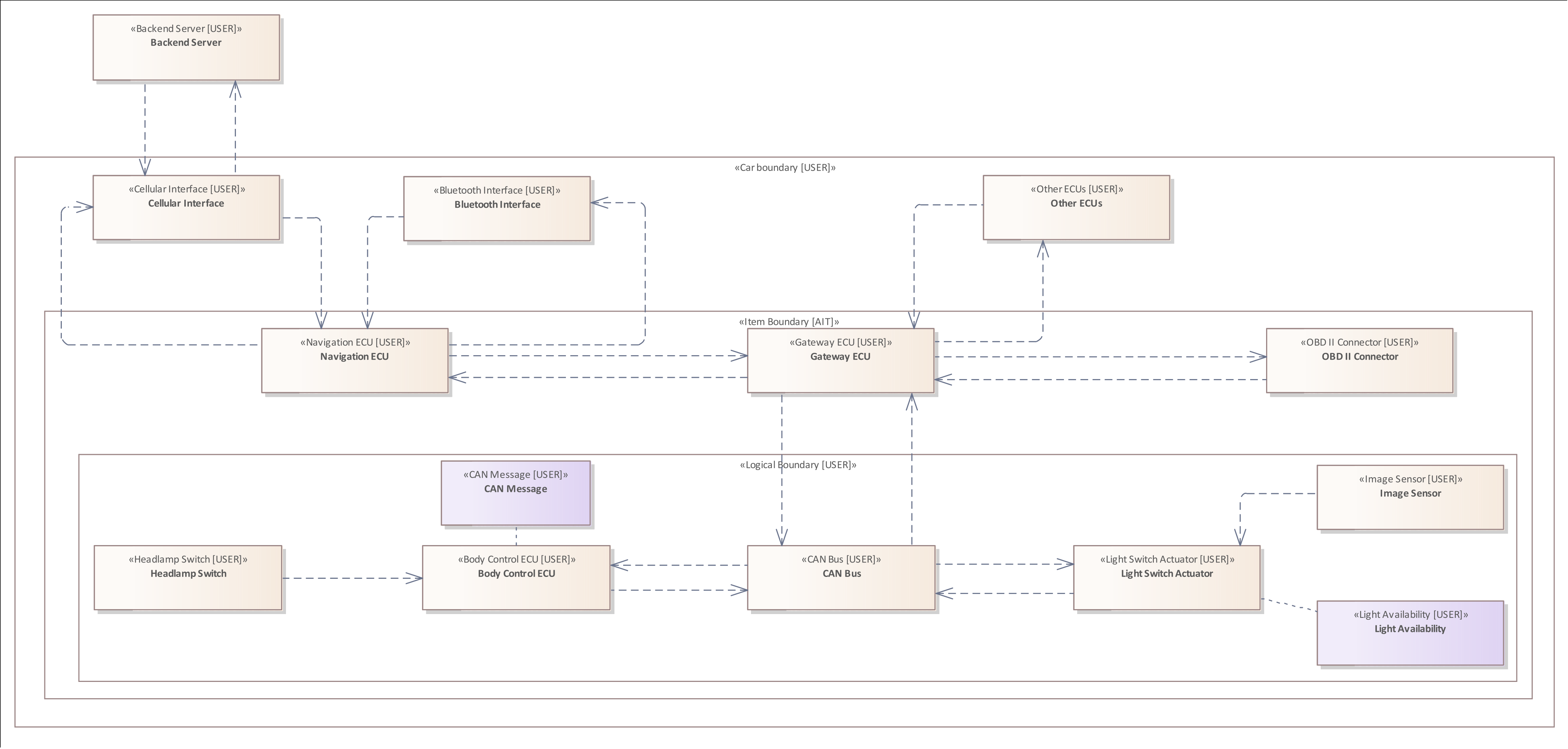
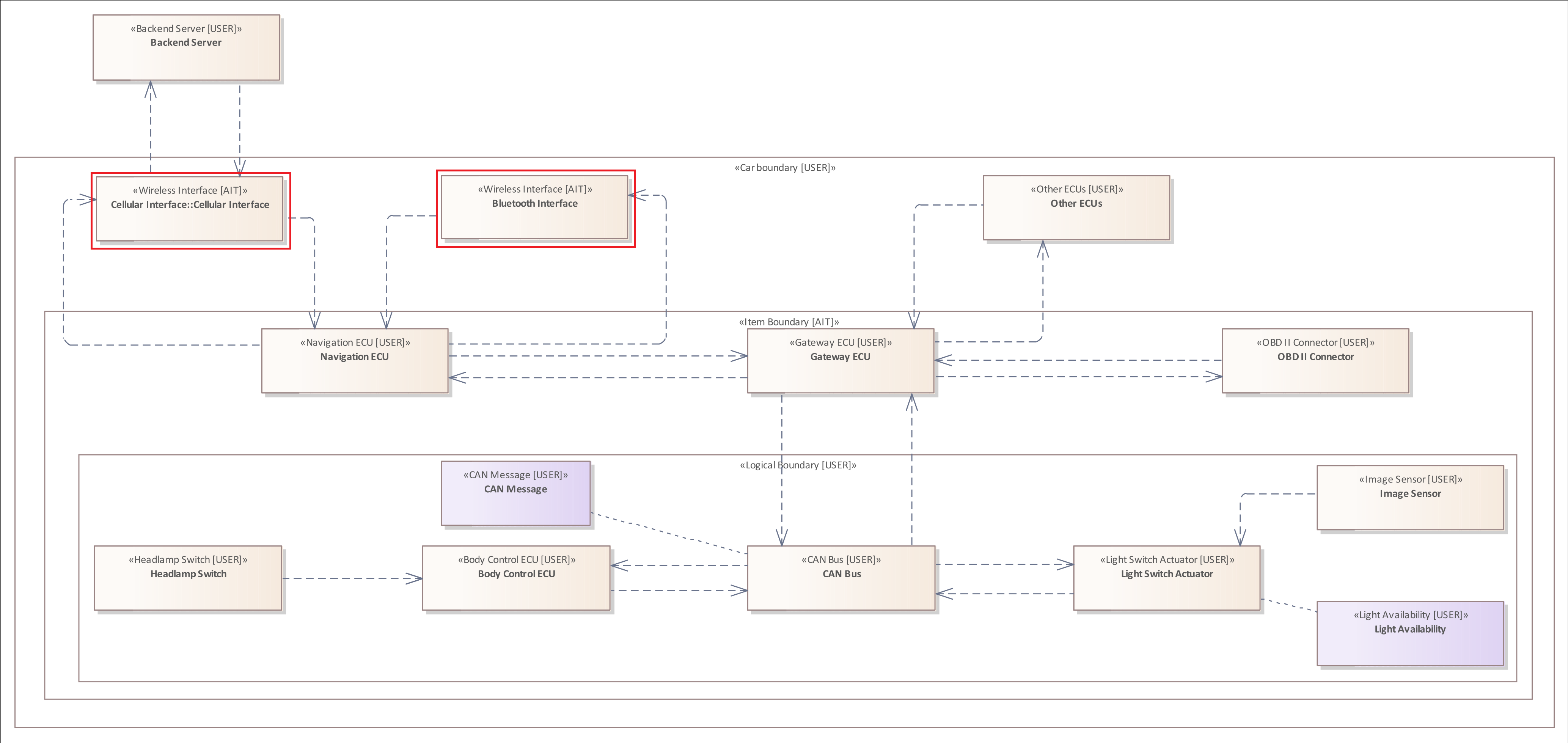
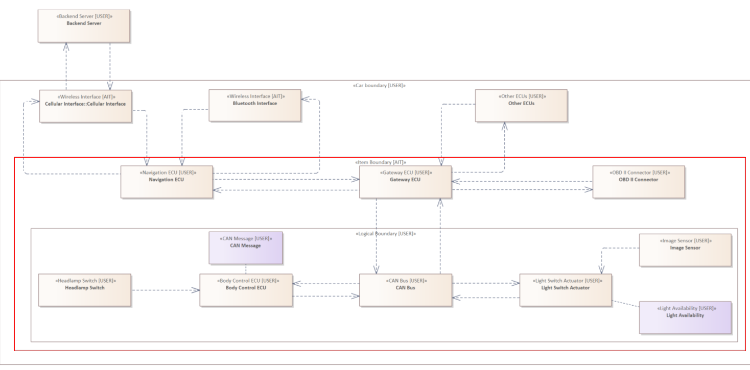
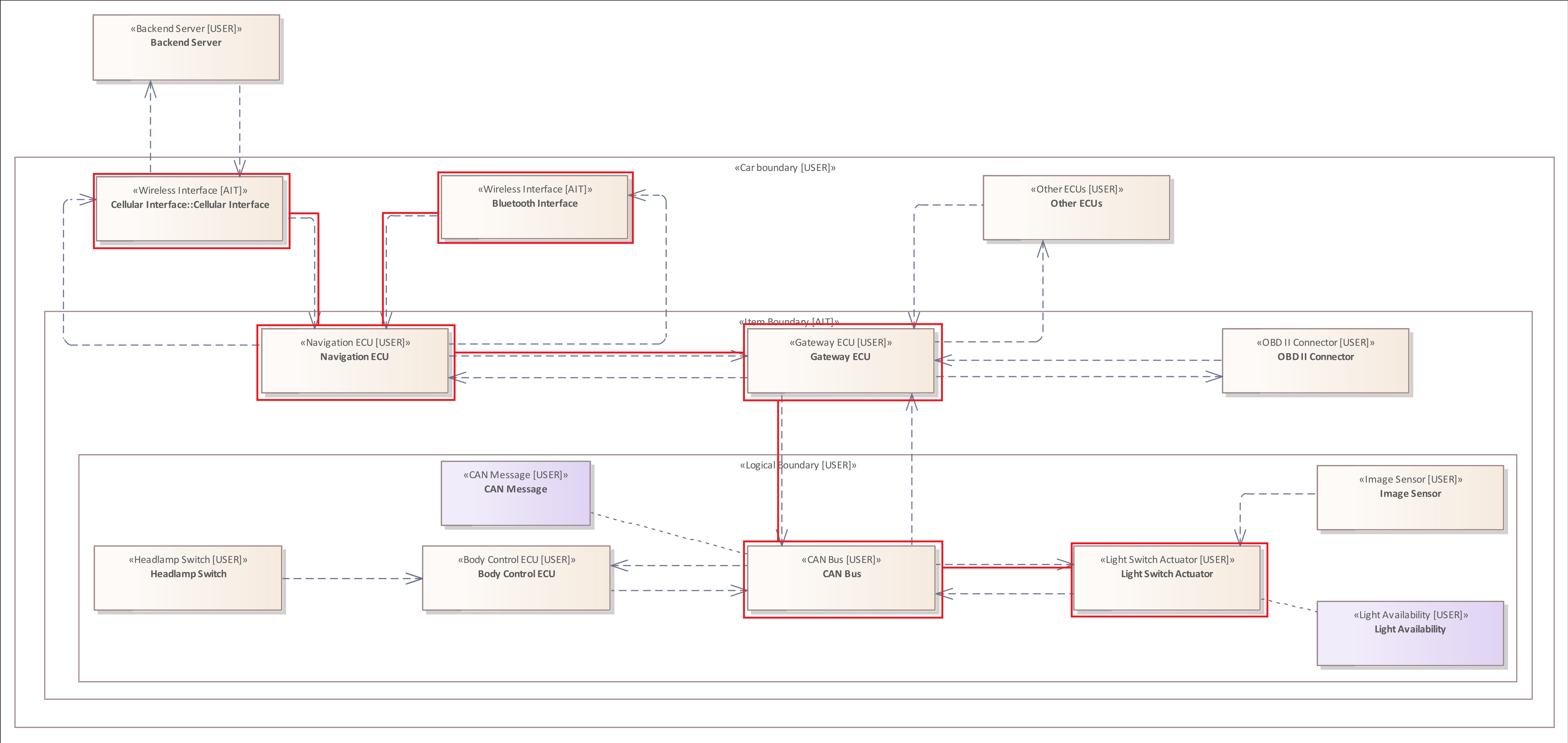
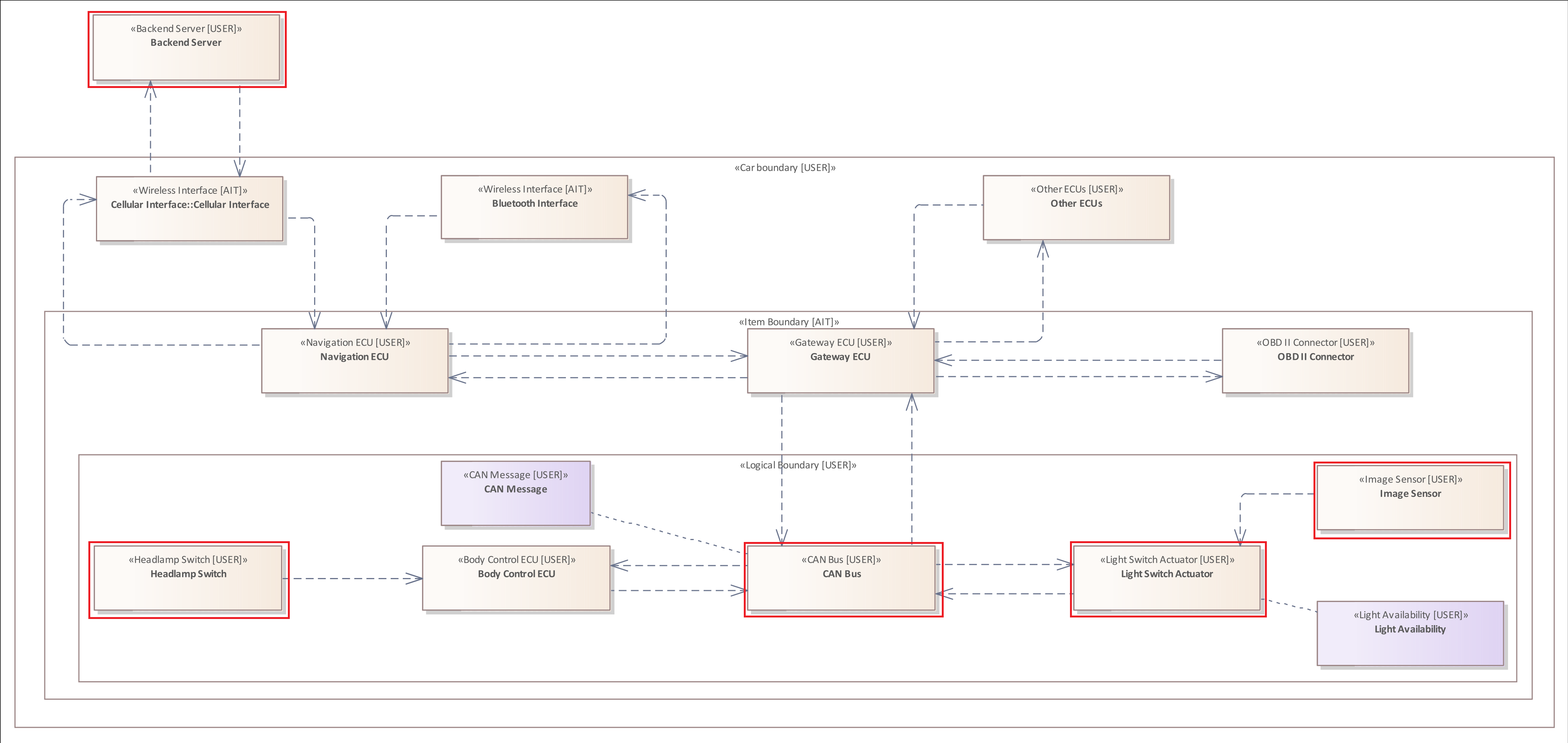
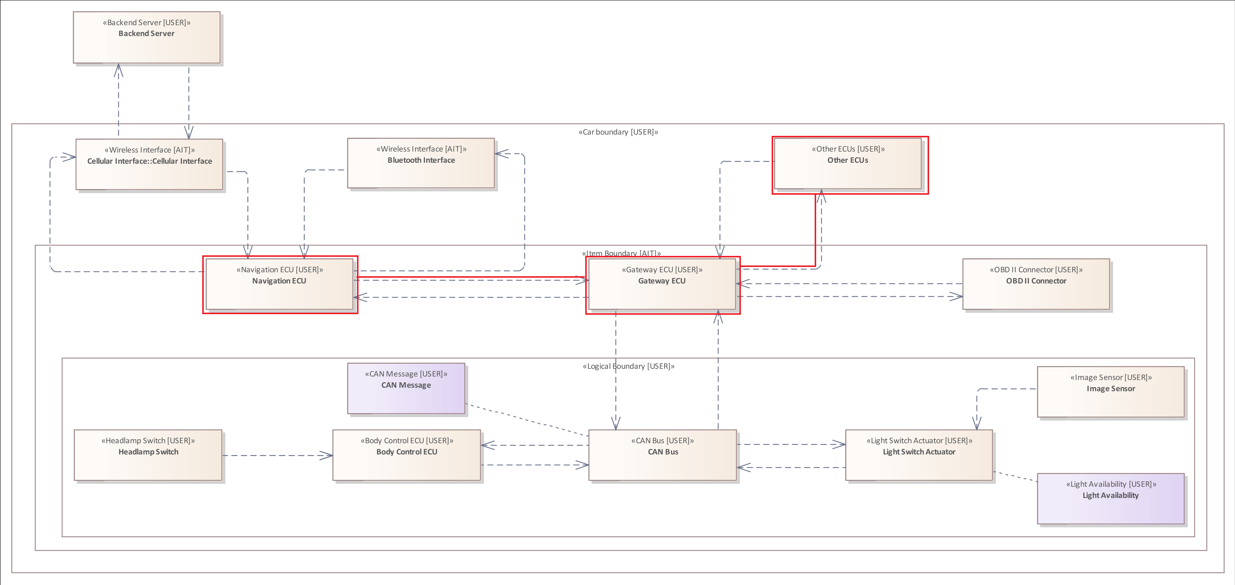
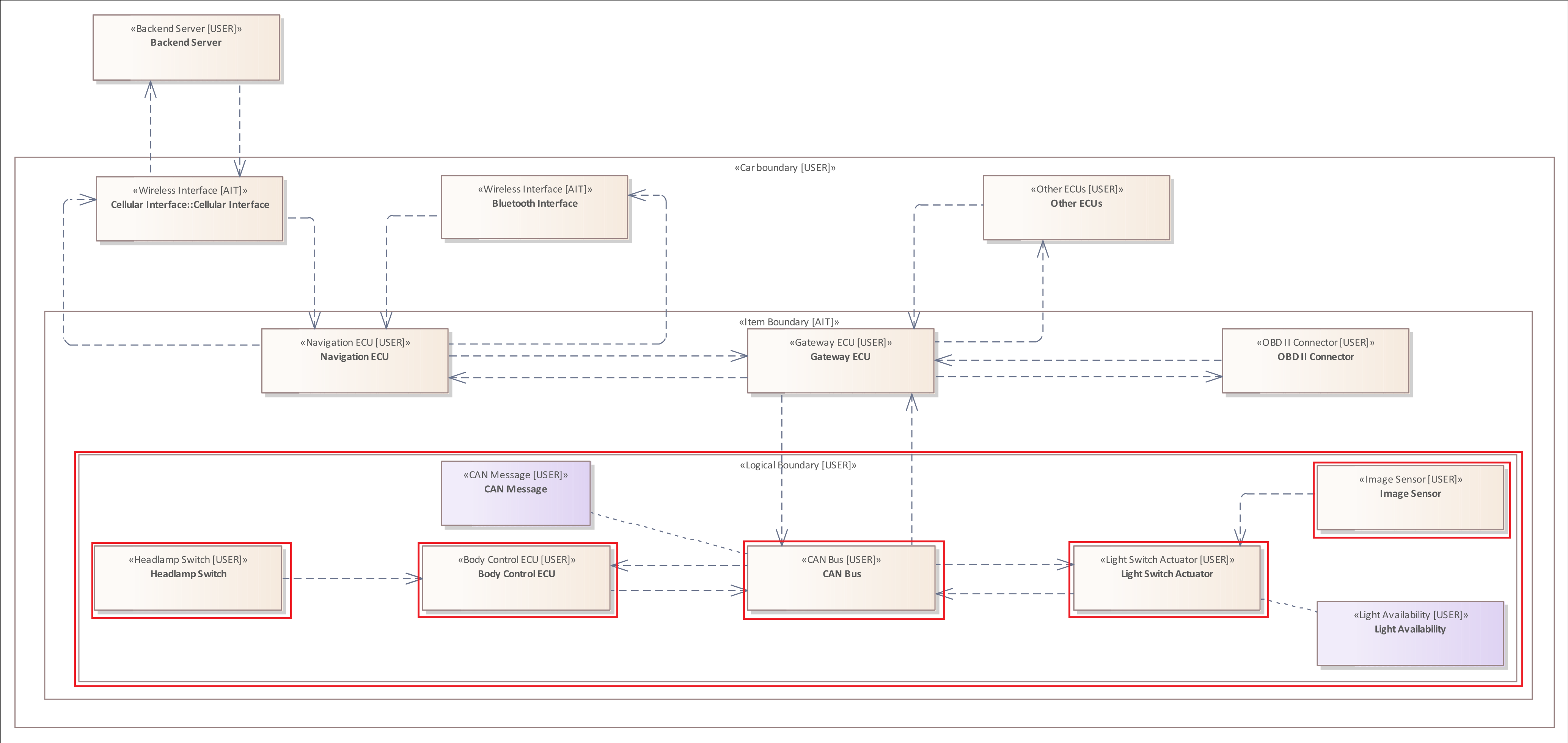
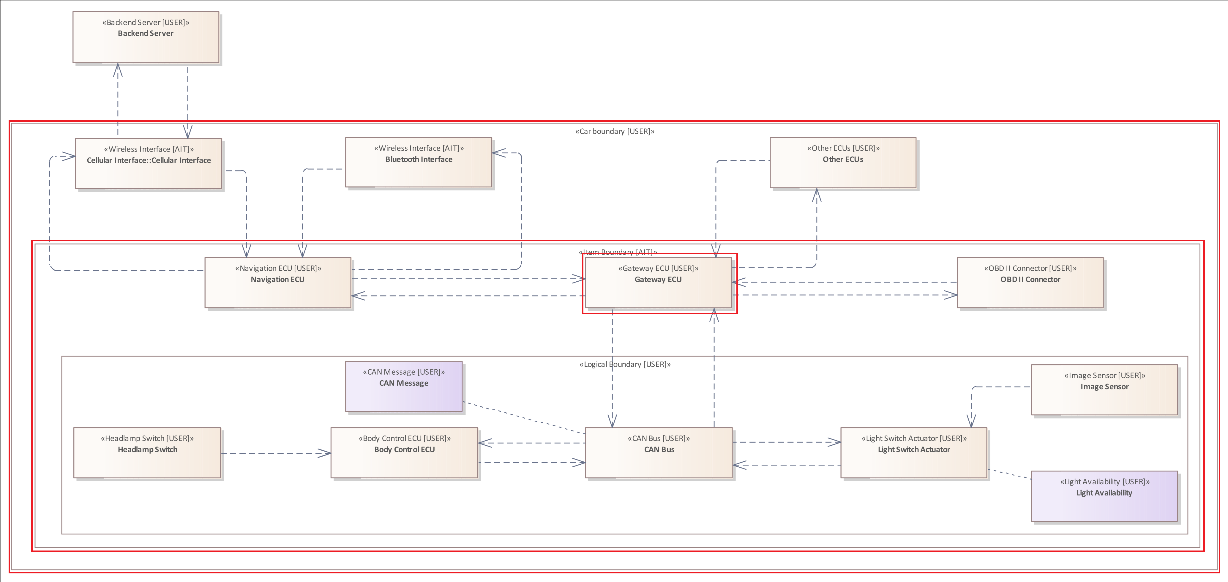
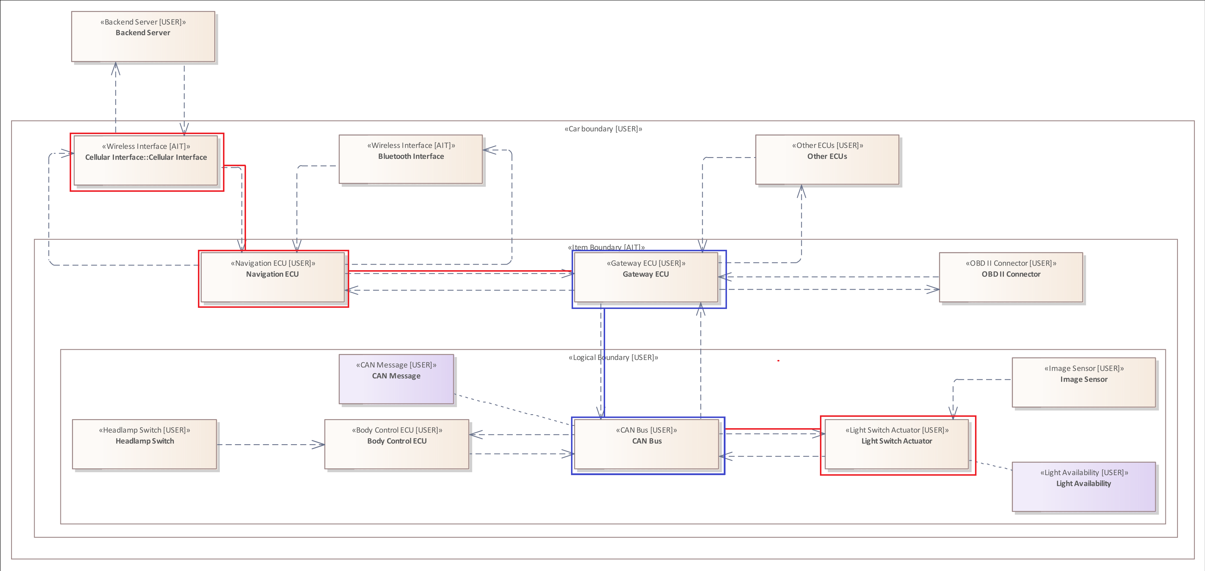
The image above shows the adopted system model from ISO/SAE DIS 21434 page 82, modeled in Enterprise Architect.
In this documentation, we show how to use the analysis language of THREATGET based on the presented system model. Furthermore, the use case example demonstrates how cybersecurity-critical information can be transferred into the formal analysis language to be used for automated analysis.
Before that, we describe the individual diagram components and what this model represents on a higher abstraction level.
The use case diagram displays a selected part of the entire internal electronic infrastructure of a vehicle. It is intended to illustrate a fictitious scenario in which an attacker attempts to influence the behavior of the "Headlamp System" of a vehicle negatively.
Note: The definition of diagram components is described in the Administration/Managing Elements section.
The diagram contains three Boundaries : "Car Boundary", "Item Boundary", "Logical Boundary". Together they encompass almost all components and describe different levels of membership within the system.
Boundaries are modeled to describe a separation between logically, physically, or legally separate operating system elements.
- Car Boundary: Describes the physical hull of the vehicle. It includes all diagram components except the "Backend Server" element in the left upper corner.
- Item Boundary: It includes all system components that are directly or indirectly involved in controlling or displaying the light settings.
- Logical Boundary: It includes only those components that are directly related to the adjustment of the light.
Usually, a boundary is used to represent a border between two interacting elements with different levels of privilege. They are usually also used to depict potential attack surfaces and simplify the analysis as they indicate possible attack points.
The original system model of ISO/SAE 21434 does not include the "Car Boundary". This boundary was added to clearly show which elements are located in the vehicle's physical envelope and are therefore not directly accessible to an attacker. Another adjustment concerns the "Logical Boundary" which is declared as "Headlamp System" in the original diagram.
The diagram contains several element components whose functions and types are described in the following listing. The labels displayed for the elements are only the names of the elements, which can be freely chosen by the user while constructing the diagram. The names of the elements are irrelevant for the analysis, only their component types. Therefore, the exact types are highlighted in the brackets in each case in the following list.
We use the following notation: Label (Top Type / Sub Type) : "Further Description".
- Backend Server (Backend / Update Server): A server which provides software updates for the vehicle. These updates are transmitted to the vehicle via a wireless connection (Wireless Flow).
- Cellular Interface (Interface / Wireless Interface): A wireless interface that connects the vehicle to the regular mobile network. It handles the incoming and outgoing data of the vehicle. For example, updates incoming from Backend Server.
- Bluetooth Interface (Interface / Wireless Interface): A wireless interface that allows drivers to connect e.g. their smartphone to the vehicle.
- Navigation ECU (Electronic Control Unit / Communication ECU): Manages the direct connections to the externally accessible interfaces of the vehicle. Therefore, it is responsible for the incoming and outgoing data traffic. For example, a driver connects his mobile phone via Bluetooth to use the hands-free system during a call. It is also responsible for the data displayed on the dashboard, such as speed and light settings.
- Gateway ECU (Electronic Control Unit / High Performance ECU): Connects several communication channels of various sources and forwards the transmitted data in the defined direction of the receiver. For example, it transmits the vehicle speed or the engine temperature to the navigation control unit that displays the information for the driver.
- Other ECUs (Electronic Control Unit / Electronic Control Unit): A vehicle has many different electronic control units (ECUs). Each additional functionality, such as measuring the air temperature and controlling the air conditioning, requires its own electronic control unit. These are also modeled outside the Item Boundary, as they do not take an active role in the Headlamp System but are directly connected to the Gateway ECU within the Item Boundary.
- OBD-II Connector (Interface / Wired Interface): A physical interface accessible from inside the vehicle. OBD is the abbreviation for On-Board-Diagnosis. This interface is used to read out diagnostic trouble codes and general fault codes to validate that all system components are operating correctly. The analysis data is transmitted from the entire system via the Gateway ECU to this interface. Furthermore, it is also possible to install software updates via this interface.
- Headlamp Switch (Interface / Human Machine Interface): Represents the physical lever or switch right next to the steering wheel. It allows the driver to adjust or switch the lights on and off.
- Body Control ECU (Electronic Control Unit / Communication ECU): Monitors all other settings made by the driver, such as the operation of the indicators or the windscreen wipers. It forwards the changes to the respective actuators.
- CAN BUS (Communication Element / Wired BUS Communication Element): Represents the CAN Communication Network within the vehicle.
- Light Switch Actuator (Actuator / Actuator): Receives the incoming requests regarding the light setting and adjusts the light accordingly.
- Camera (Sensor / Image Sensor): The vehicle has a camera that faces in the direction of travel and detects oncoming vehicles. If the headlights are switched on, and a vehicle approaches, this control unit sends a dimming command to the Light Switch Actuator. As soon as the other vehicle is no longer in the field of vision of the camera, the lights are turned back on to original brightness.
It is essential to understand that the electronic control units are not individually connected. Instead, they communicate via a shared Control Area Network, also called CAN BUS. This network can be understood as the nervous system of the automobile and the individual ECUs as individual body parts.
The diagram contains two different types of Connectors. All Connectors are also referred to as "Data Flows". The presented vehicle, contains only Wired Flows, i.e. elements that are connected via a cable. The only Wireless Flows describe the communication between the Backend Server and the Navigation ECU.
The diagram contains two Assets represented by crosshair icons. Assets describe something of value to a stakeholder with the respective cybersecurity property, impact category, and impact level. The CAN Message asset represents a data message that is exchanged within in the vehicle. The Light Availability asset indicates that the light of a vehicle should always be under control of the driver.
Threat Model
Table G.6 on page 86 of the ISO/SAE 21434 standard lists the identified threats for the use case example. One of the specified threats refers to the loss of integrity of a CAN Message. An attacker could violate the integrity of a CAN Message, controlling the light by injecting unauthorized malicious messages into the network. This spoofing attack can force the headlights to turn off unexpectedly. While driving at night or in poor light conditions, this may lead to a severe accident.
The standard describes several possible attack scenarios. One of them, which is used in the following to introduce the analysis language, is described below:
The attack scenario describes an exploit of the Cellular Interface to access the internal network of the vehicle. If the interface does not implement an authentication or input validation mechanism, the attacker is able to transmit malicious data to the vehicle.
The special characteristic of this attack path is the distance of the attacker from the attacked object. As described in the previous section: the Cellular Interface connects the vehicle to the regular mobile network. Therefore, the adversary can act remotely and thus not endanger himself.
Once the malicious data, e.g. a manipulated firmware, has been transmitted, the Navigation ECU could be compromised due to its direct connection to the interface. Via the compromised control unit, the attacker gains access to the internal CAN BUS network. This enables the attacker to read the exchanged data on the network if it is not encrypted, manipulate messages if they do not have tamper protection, or inject manipulated messages. In the particular scenario described in the standard, malicious CAN Messages are injected. These are addressed to the Light Switch Actuator and transport the request to turn off the lights. If the Gateway ECU does not implement a restriction on forwarding data, the message reaches the Light Switch Actuator and influences the behavior of the headlights.
Now that the use case example has been presented and a possible attack scenario has been described, the following sections show how the analysis language of THREATGET can be used to perform an automated analysis. The examples that relate to this attack scenario are marked within the sections:
- Identify the Wireless Interface
- Using the Tagged Value Filter to distinguish the wireless interfaces
- Using multiple Tagged Value Filters to narrow the threat
- Analyze the data connection to the Navigation ECU
- Hack the Navigation ECU
- Injecting a malicious CAN Message, that is forwarded to the Light Switch Actuator
The Analysis Language of THREATGET
The threat model is based on a set of rules that can also be defined within the web interface. The rules are specified using a "Domain-Specific Language", which will be described throughout the following sections. The rules are based on previously defined diagram components, because only what is known can be queried.
A rule consists of a title, a description, an assigned threat type, an impact estimation, a likelihood estimation, and, most importantly, the so-called anti-pattern.
The anti-pattern represents the heart of every rule. It expresses threats in a human as well as machine-readable language. Each anti-pattern describes an undesirable condition inside a system.
The analysis language is essentially based on five patterns, each referring to one of the diagram components. This approach ensures that the language remains modular and can be extended as required. The language structure has been inspired by the data format JSON. It requires little additional writing overhead and still offers a readable hierarchical format.
A pattern examines whether an Element, Asset, Connector, Boundary, or Flow exists within the diagram or not. An assigned type can further restrict each pattern except the Flow Pattern. The concept of Flows is explained within the corresponding pattern and filter section (Flow Pattern, Flow Filter). The assigned type indicates that a pattern only matches components of this type.
A pattern can, but does not necessarily, have filters assigned. A filter specifies additional conditions that a pattern must meet in order to correspond to a threat. Overall there exist nine different filters. These can be used, for example, to examine the assigned tagged values (properties) of a component, the connections between components, or the relationships between components.
The following picture illustrates the concept of patterns and filters.
However, due to the system model structure, not all filters can be applied to all patterns. For example, Boundaries cannot be assigned properties, so they cannot be filtered accordingly. Another example is that only Elements can be filtered by their connectors to other Elements, since Elements are the only diagram component connected via Connectors (Data Flows).
This may seem very complex initially, but all the terms used in the description will be explained throughout this document and examples. Furthermore, we link each pattern with its possible filters.
The full specification of the language can be found at the bottom of the page.
The Element Pattern
Let's start with the simplest, but most important and most frequently used pattern.
The Element Pattern allows you to examine the Elements within in the system model.
Each pattern starts with a specific keyword. The Element Pattern has the initial keyword "ELEMENT" (Element | element).
The general structure of such a rule is as follows:
- ELEMENT -> Element Pattern without any type specification or additional filters
- ELEMENT Type Filter -> Element Pattern focusing on a specific type
- ELEMENT { .... } -> Element Pattern with additional filters (...)
- ELEMENT Type Filter { .... } -> Element Pattern with type and further filters (...)
Applicable filters for the Element Pattern :
- The Type Filter
- The Tagged Value Filter
- The Asset Filter
- The Element Relation Filter Filter
- The Connector Filter
- The Flow Filter
Since the filters will be explained in the following sections, this section is limited to the use of the Element Pattern in combination with the simplest form of the Type Filter.
Example 1
Each pattern of the analysis language is initialized by a specific keyword, as described before. The keyword is already sufficient to create a valid analysis rule. The keyword "ELEMENT" indicates that all elements within the diagram should be examined.
ELEMENT
Example 2
All Elements of the diagram have a top-type and a sub-type. You can specify a typefilter for the Element Pattern, indicating that only the Elements with the specified type should be analyzed by the analysis rule.
The following rule examines only those elements that have the top-type "Interface".
ELEMENT : "Interface"
The presented vehicle contains three different interfaces:
- Cellular Interface
- Bluetooth Interface
- OBD-II Connector
Example 3
The "Wireless Interface" is a sub-type of the "Interface" top-type. Using a specific typefilter limits the results of the analysis.
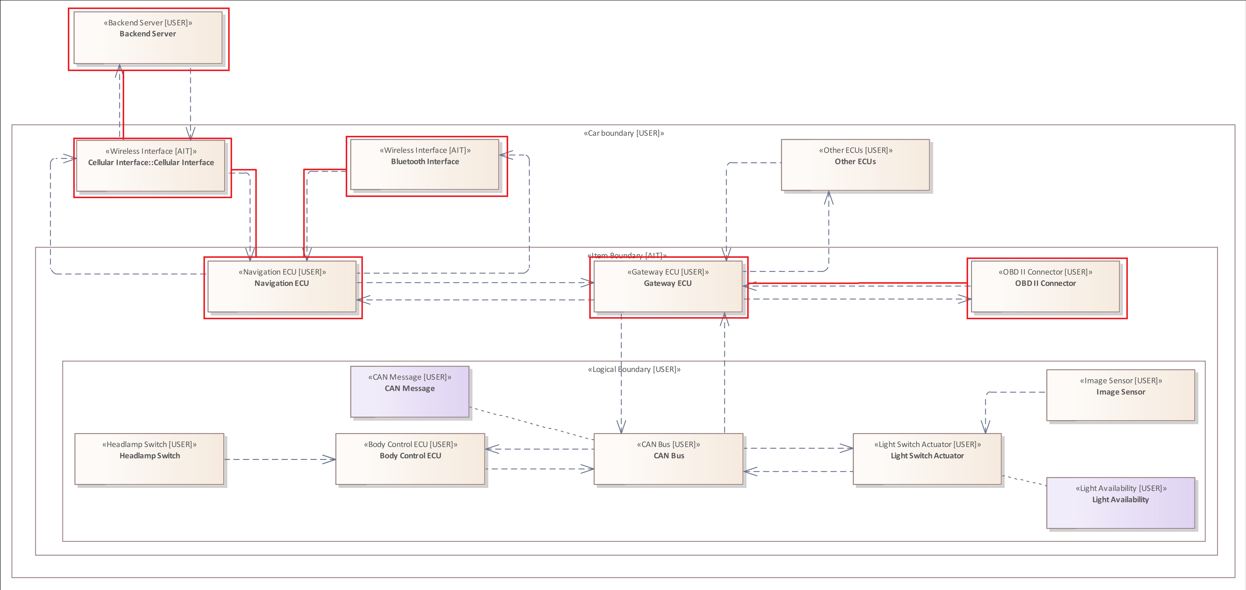
The following analysis rule is the first step into the described threat scenario. The scenario describes that an attacker can exploit a "Wireless Interface" to transmit malicious data to the vehicle.
ELEMENT : "Wireless Interface"
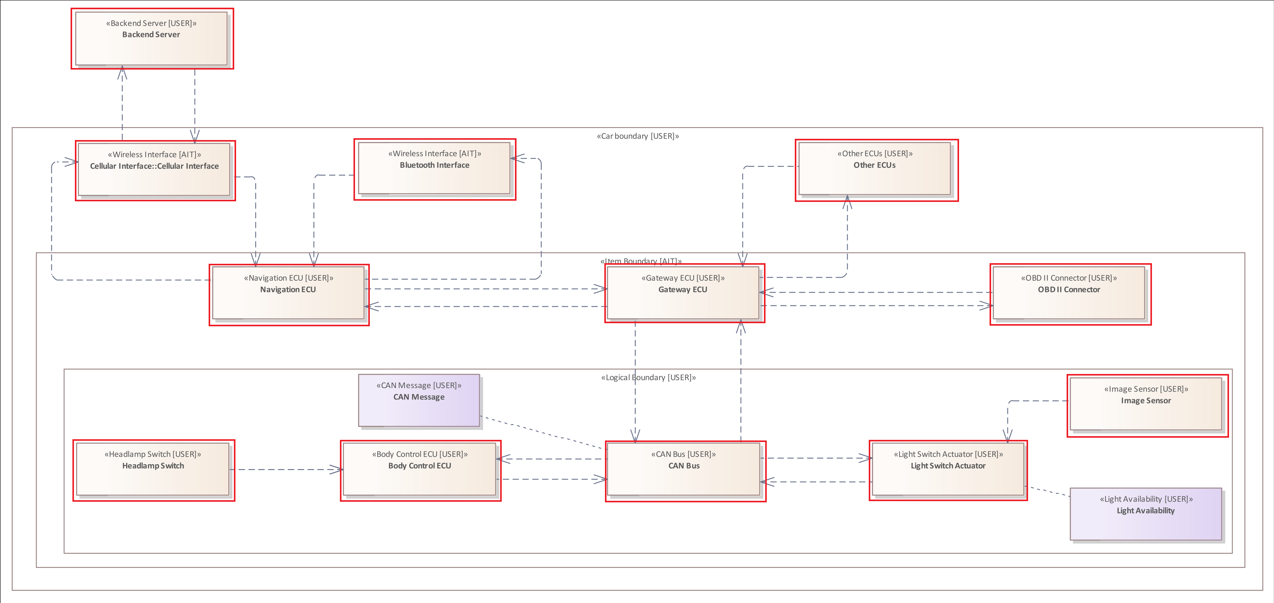
The presented vehicle contains two wireless interfaces:
- Cellular Interface
- Bluetooth Interface
The vehicle contains two Elements of the "Wireless Interface" type. However, only one of them is suitable for a long-range remote attack, as the transmission protocols used have different operational ranges and coverage. Therefore, in the third step of the threat scenario, we show how we can use the Tagged Value Filter to distinguish between these two interfaces. * Using the Tagged Value Filter to distinguish the wireless interfaces
Further Examples
ELEMENT : "Sensor"
ELEMENT : "ECU"
ELEMENT : "Communication ECU"
The Asset Pattern
The Asset Pattern allows you to examine the Assets within in the system model.
The Asset Pattern has the initial keyword "ASSET" (Asset | asset).
The general structure of such a rule is as follows:
- ASSET -> Asset Pattern without any type specification or additional filters
- ASSET Type Filter -> Asset Pattern focusing on a specific type
- ASSET { .... } -> Asset Pattern with additional filters (...)
- ASSET Type Filter { .... } -> Asset Pattern with type and further filters (...)
Applicable filters for the Asset Pattern :
- The Type Filter
- The Tagged Value Filter
It is the only pattern that cannot be used as an initial pattern for an analysis rule. This pattern can only be used within the Asset Filter. The Asset Filter, in turn, can only be assigned to the Element Pattern. Therefore, we already anticipate a little bit and add a so-called Asset Filter to an Element Pattern.
Example 1
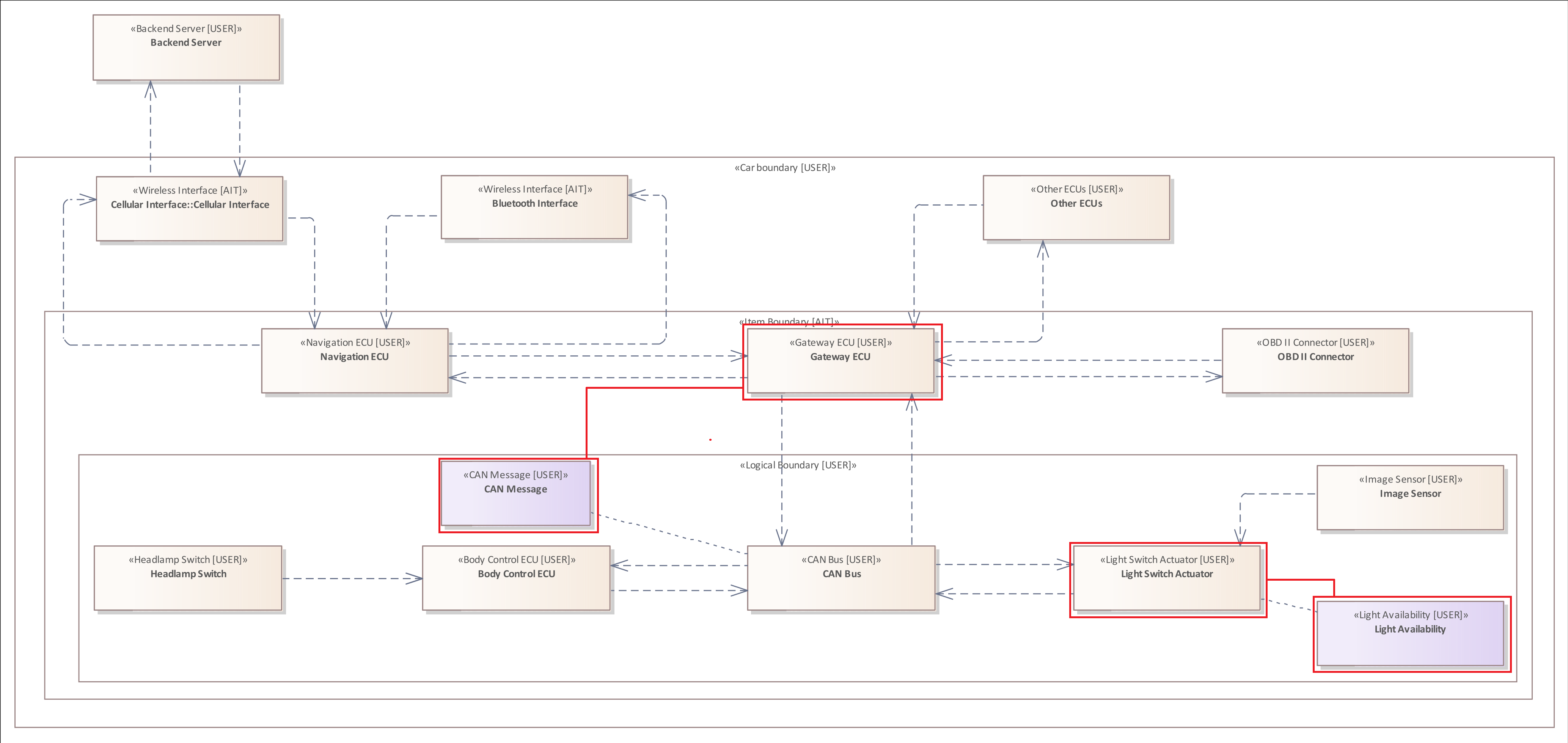
The following analysis examines all elements that are linked to an asset with the assigned type "CAN Message".
ELEMENT {
    HOLDS ASSET : "CAN Message"
}
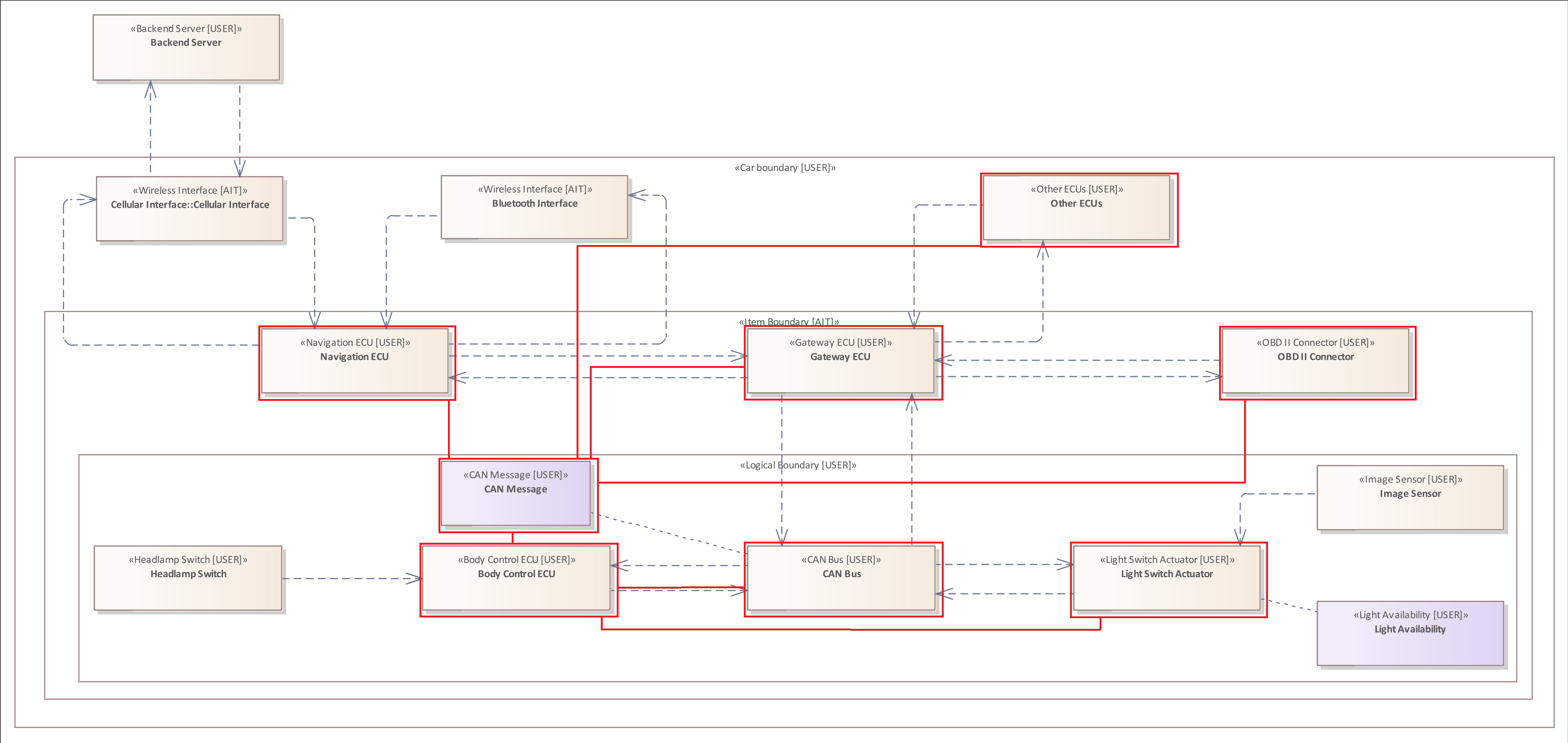
As described in System Model, the internal communication of the vehicle runs exclusively via so-called "CAN Messages". Within the diagram, the links of the "CAN Message" Asset are normally hidden in order to avoid overloading the diagram. For this example, the Asset Connectors are displayed to clearly visualize the result of the analysis. This analysis shows which Elements are linked (HOLD) to the "CAN Message" Asset.
The typefilter of the Asset Pattern works the same as the ELEMENT Pattern. If the type filters were omitted, the "Light Swich Actuator" Element and the "Light Availability" ASSET would also be marked.
Further Examples
The following rule examines all Elements of the type "Electronic Control Unit" that are linked to an ASSET of the type "CAN Message"
ELEMENT : "ECU" {
    HOLDS ASSET : "CAN Message"
}
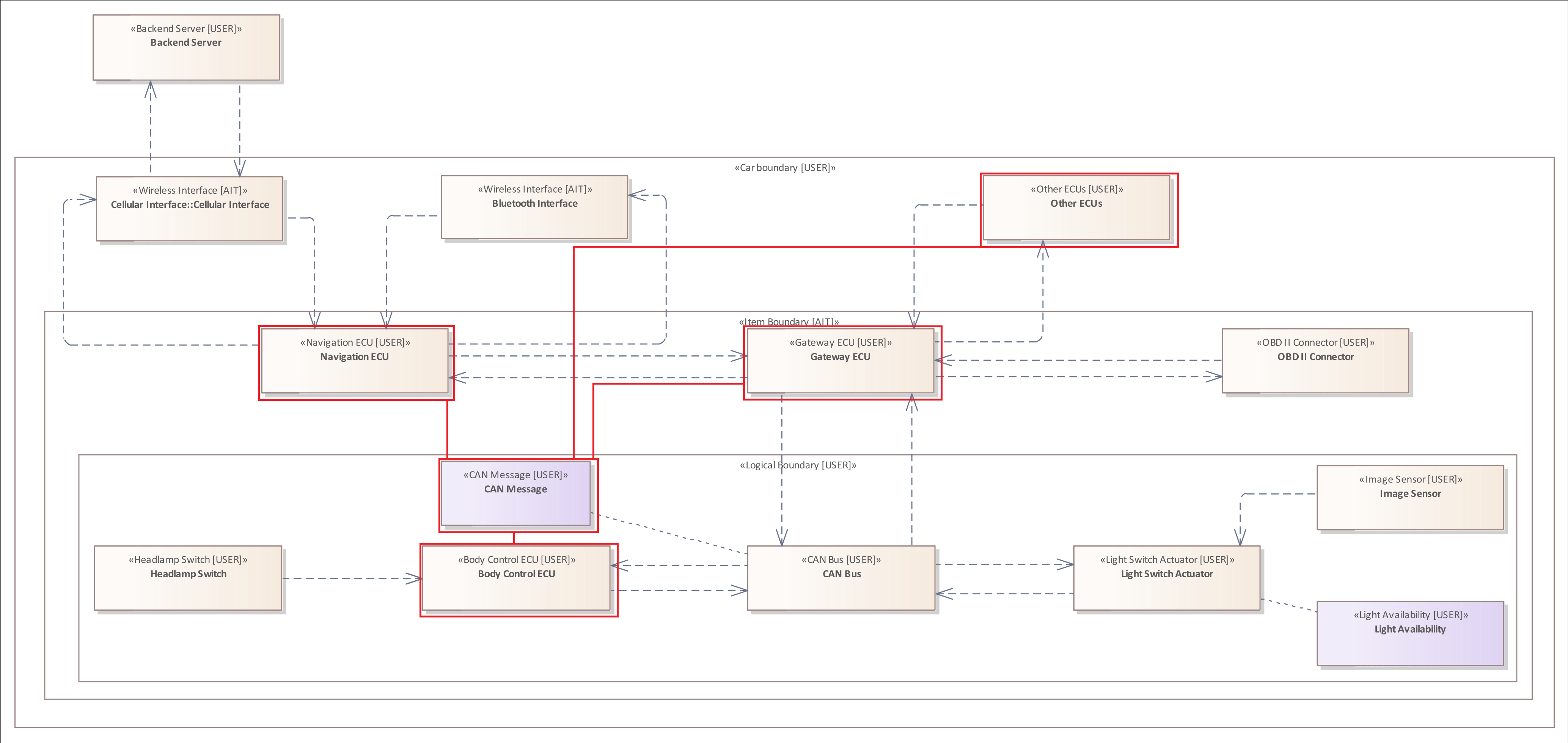
Compared to the previous rule, the "CAN BUS" and the "Light Switch Actuator" are not marked as they are not of the type "Electronic Control Unit".
The Boundary Pattern
The Boundary Pattern allows you to examine the Boundaries within in the system model.
The Boundary Pattern has the initial keyword "BOUNDARY" (Boundary | boundary).
The general structure of such a rule is as follows:
- BOUNDARY -> Boundary Pattern without any type specification or additional filters
- BOUNDARY Type Filter -> Boundary Pattern focusing on a specific type
- BOUNDARY { .... } -> Boundary Pattern with additional filters (...)
- BOUNDARY Type Filter { .... } -> Boundary Pattern with type and further filters (...)
Applicable filters for the Boundary Pattern :
- The Type Filter
- The Boundary Relation Filter
The Boundary Pattern has only one filter, as boundaries have no tagged values, cannot be linked to Assets or connected to other Elements. Therefore, there is only one filter that can examine the relationship of the Boundary to other Boundaries or Elements.
Example 1
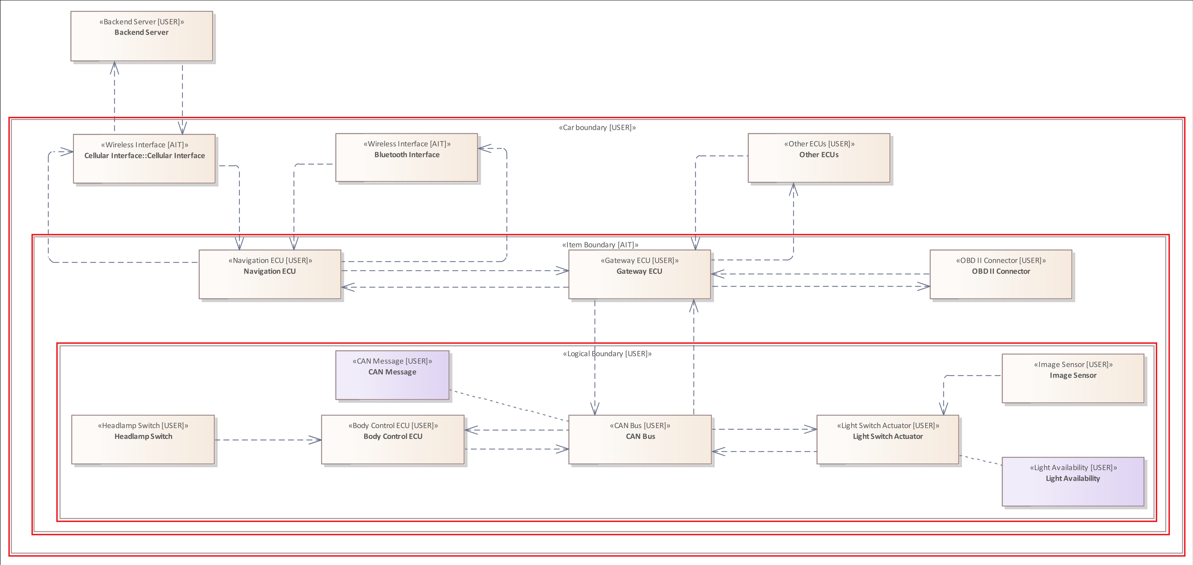
The following rule is used to examine all Boundaries within the system model:
BOUNDARY
Example 2
Similar to the Element Pattern you can use an additional type-filter to restrict the results of the analysis.
The following rule is used to examine all Boundaries of the type "Item Boundary" within the system model:
BOUNDARY : "Item Boundary"
The Connector Pattern
The previous patterns of the analysis language were used to analyze single diagram components.
The Connector Pattern is used to analyze the direct connections between two Elements.
The Connector Pattern has the initial keyword "CONNECTOR" (Connector | connector).
Since a Connector always connects two Elements, each Connector Pattern contains a mandatory Source Filter and a Target Filter. These are added to the pattern inside the curly brackets.
The general structure of such a rule is as follows:
- CONNECTOR { Source Filter & Target Filter}
- CONNECTOR Type Filter { Source Filter & Target Filter}
- CONNECTOR { Source Filter & Target Filter & ... }
- CONNECTOR Type Filter { Source Filter & Target Filter & ... }
Applicable filters for the Connector Pattern :
- The Source Filter -> Mandatory
- The Target Filter -> Mandatory
- The Tagged Value Filter
- The Asset Filter
- The Crosses Filter
In the early stages of the analysis language development, Source Filter and Target Filter were optional. Over time, we decided to make them mandatory because it makes sense to think about where a Connector originates and where it terminates. Many threats to systems exist in their Connectors, especially in those that cross a Boundary, because Elements, which communicate across that border, disclose an attack surface or have different privilege levels. Furthermore, source and target of a Connector Pattern are part of the analysis result.
The Connector Pattern is similar to the Connector Filter that can be added to the Element Pattern.
The Source Filter
The Source Filter is used to specify where a Connector originates from.
The following rule examines all Connectors that originate from an "Interface".
CONNECTOR {
    SOURCE ELEMENT : "Interface" &
    TARGET ELEMENT
}
The system model contains three Elements with the top-type "Interface". The target Element is not further specified, therefore, the Connector can terminate at any Element.
The Target Filter
The Target Filter is used to specify where a Connector terminates.
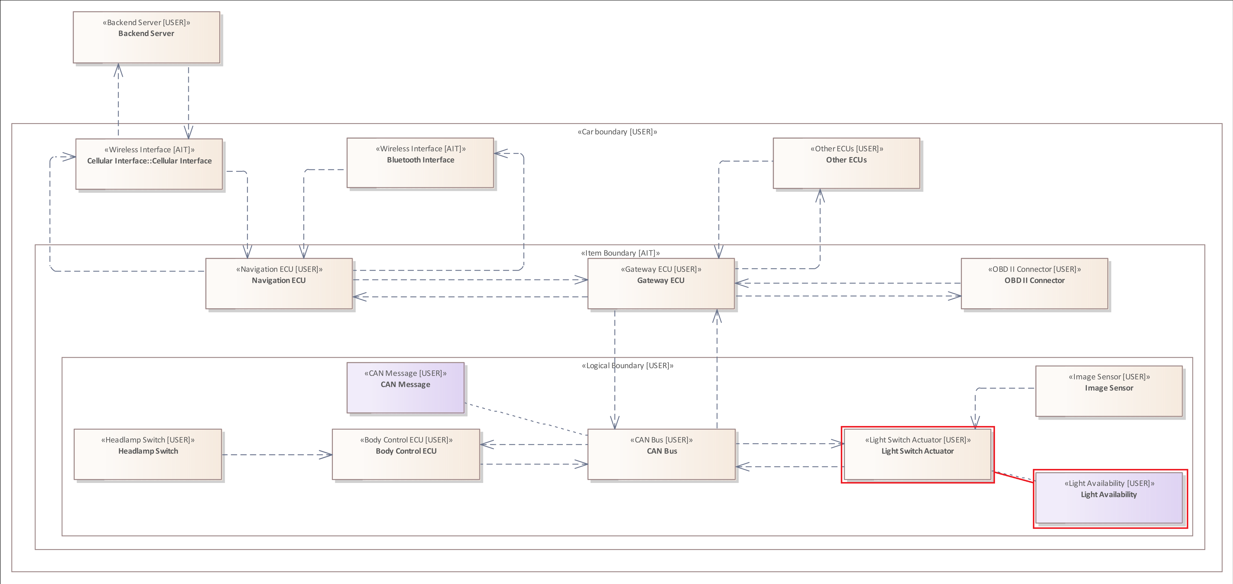
The following rule examines all Connectors that target the "Light Switch Actuator" (top-type = "Actuator", "Light Switch Actuator" is only the label).
CONNECTOR {
    SOURCE ELEMENT  &
    TARGET ELEMENT : "Actuator"
}
The system model contains one Element with the top-type "Actuator". The source Element is not further specified, therefore, the Connector can originate from any Element.
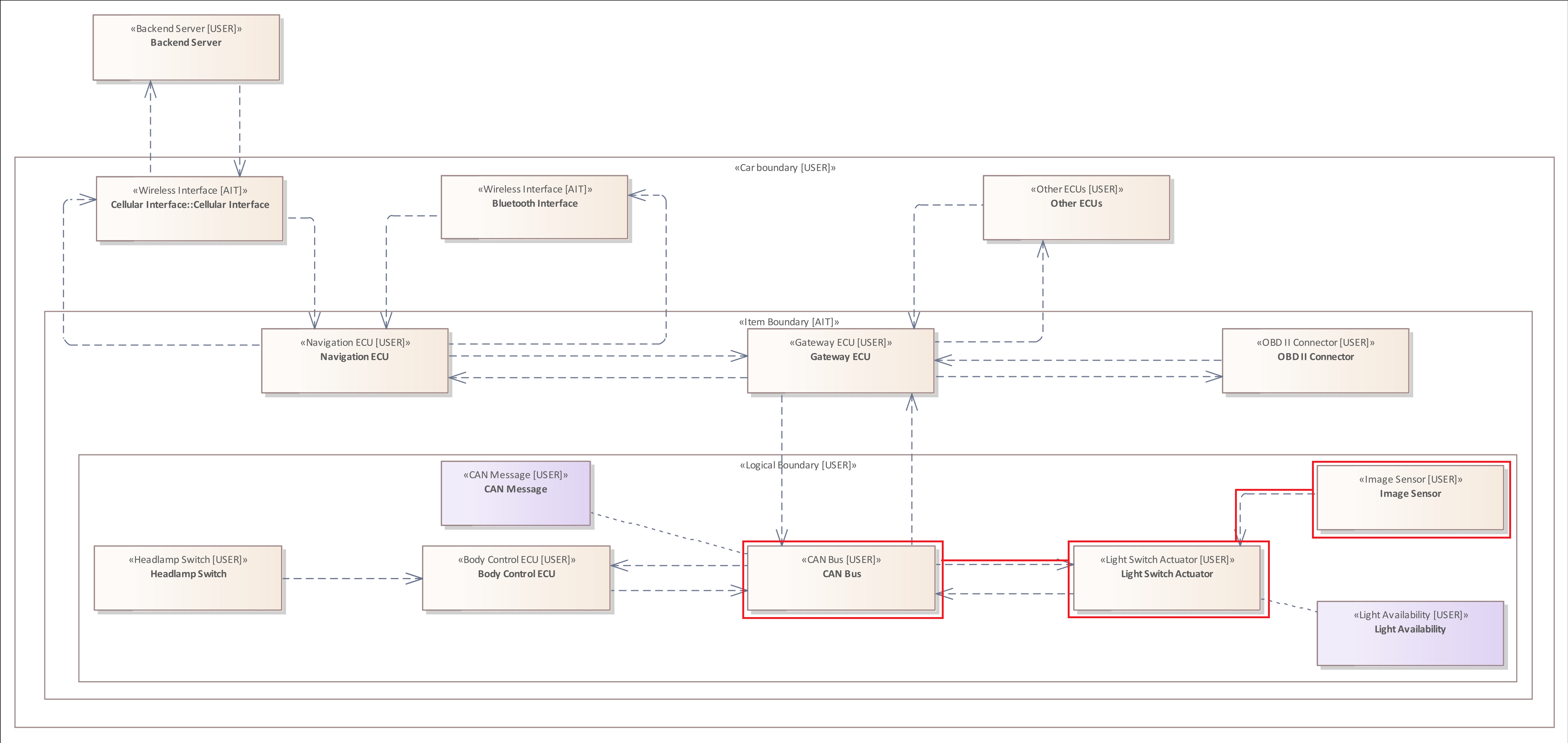
Please note that the Asset and the Connector to the "Light Switch Actuator" are not marked. This is due to the fact that this Asset is only linked to the Element not logically connected to transfer data.
Example 1
The following rule examines all Connectors within the system model, since the Connector Pattern does not have a specific type, and neither does the Source Filter and the Target Filter.
CONNECTOR {
    SOURCE ELEMENT  &
    TARGET ELEMENT
}
The result of this analysis rule would include all elements and all connectors of the system model.
Example 2
The following rule examines all Connectors of the type "Wireless Flow" within the system model.
Connector is the diagram component name. "Wireless Flow" is the assigned type.
CONNECTOR : "Wireless Flow"{
    SOURCE ELEMENT  &
    TARGET ELEMENT
}
The only Connectors that fulfill this type filter are communicating with the "Cellular Interface", since all other Connectors inside the vehicle are of type "Wired Flow".
Both Connectors are marked, since Source Filter and Target Filter include no type specification.
The Flow Pattern
The previous Connector Pattern can be used to analyze direct connections between two Elements.
The Flow Pattern is used to analyze connections between two Elements with several intermediate steps without explicit definition.
A Flow is defined as an alternating sequence of Elements and Connectors, starting with an Element and ending at an Element. By this definition, even a single Connector constitutes a Flow.
The Flow Pattern is very similar to the Connector Pattern as it has also a mandatory Source Filter and Target Filter. However, the Flow Pattern is the only pattern that cannot be assigned a type filter because it consists of two different diagram components.
The Flow Pattern has the initial keyword "FLOW" (Flow | flow).
Since a Flow consists of Connectors and connects two Elements, each Flow Pattern also contains a mandatory Source Filter and a Target Filter. These are added to the pattern inside the curly brackets.
The general structure of such a rule is as follows:
- FLOW { Source Filter & Target Filter}
- FLOW { Source Filter & Target Filter & ... }
Applicable filters for the Flow Pattern :
- The Source Filter -> Mandatory
- The Target Filter -> Mandatory
- The Crosses Filter
- The Includes Filter
The Flow Pattern is similar to the Flow Filter that can be added to the Element Pattern.
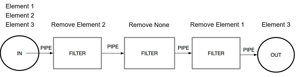
Flow Pattern Explained
The image below illustrates the concept behind a Flow in more detail.
On the left side is the Source Element and on the right side the Target Element. In between there are several Elements which are not specified more precisely, but which are all connected by Connectors.
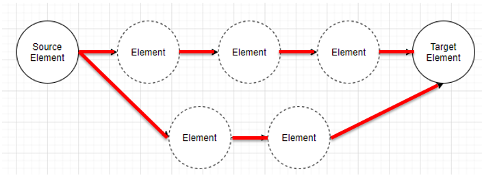
During the analysis of a Flow pattern all Flows, also called paths, between two Elements are searched and returned as analysis result.
In order to prevent infinite loops, each Flow/Path may contain each Element only once. This ensures that modeled loops in the system model do not affect the analysis procedure.
Example 1
The following rule examines all Flows within the system model.
Flow {
    SOURCE ELEMENT  &
    TARGET ELEMENT
}
The syntax is quite similar to the Connector Pattern. However, the analysis result is different, as the Flow Pattern does not only analyze direct connections, but all paths between each Element and all other Elements.
Therefore, we encourage every user of this analysis language to think about the possible Source Element and Target Element of a Flow Pattern to avoid overflowing analysis results.
Example 2
The Flow Pattern cannot be assigned a type-filter. However, it can be assigned to the Source Filter and the Target Filter
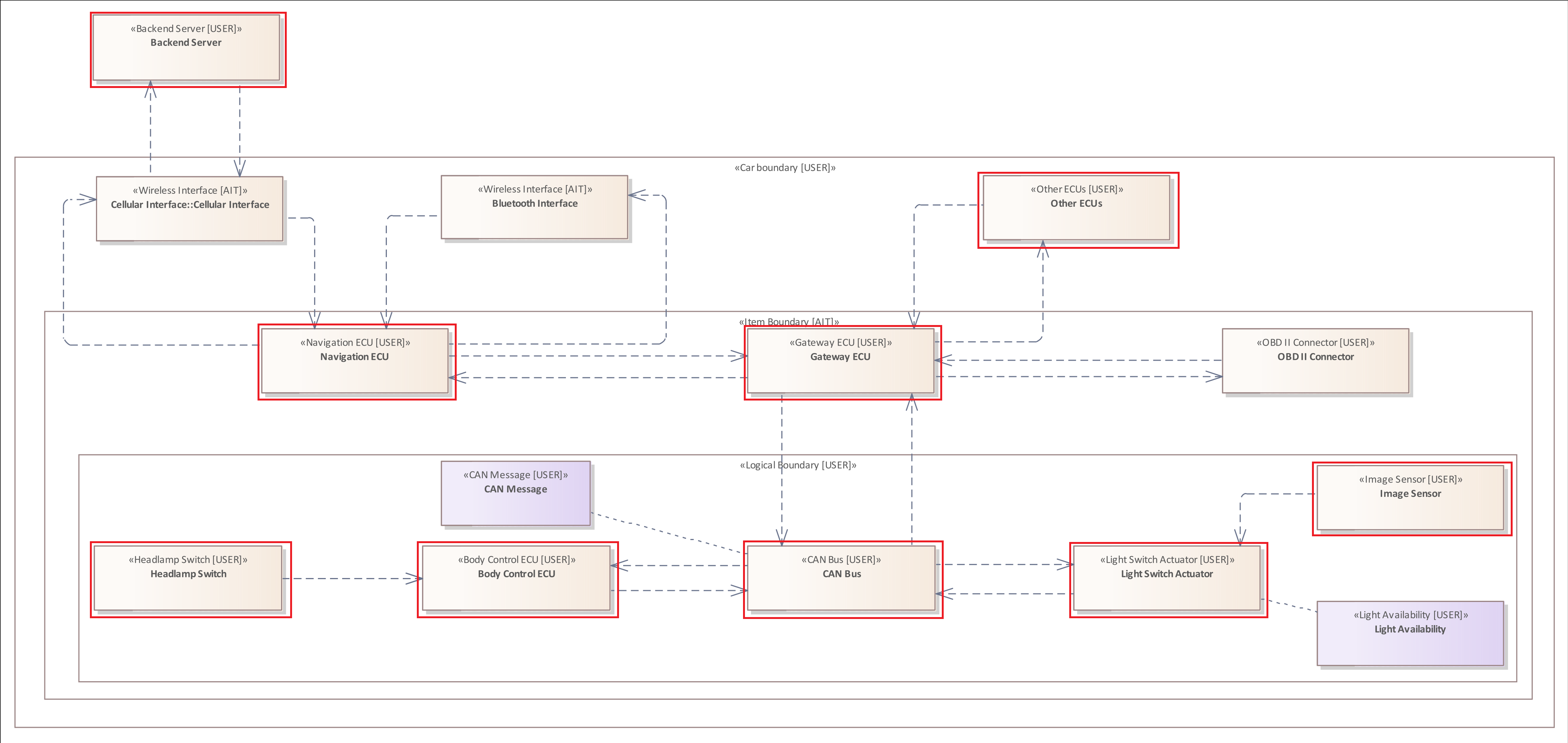
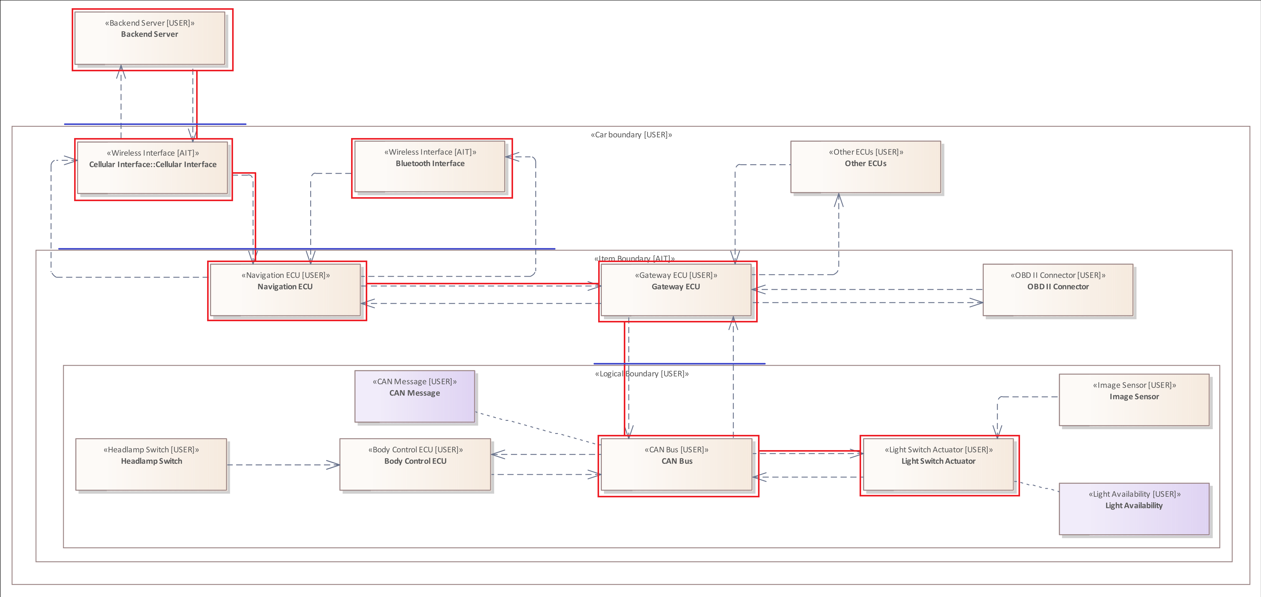
The following rule examines all Flows within the system model between a "Wireless Interface" and an "Actuator".
Flow {
    SOURCE ELEMENT "Wireless Interface" &
    TARGET ELEMENT "Actuator"
}
The system model contains two "Wireless Interfaces" and one "Actuator". The system model above shows the Flows between these Elements.
The Type Filter
In the previous patterns and filter the simplest form of the Type Filter was already introduced. It was shown how this filter can be used to check the respective diagram components for their top and subtypes. However, the Type Filter can be extended to analyze different situations of patterns. For example, to define that an anti-pattern can also apply to multiple diagram components of different types.
General Structure:
- : "Type"
- : != "Type"
- : IN ["Type", "Type", ... ]
- : NOT IN ["Type", "Type", ... ]
The Tagged Value Filter can be added to the following patterns and filter:
- The Element Pattern
- The Asset Pattern
- The Boundary Pattern
- The Connector Pattern
- The Connector Filter
Example 1
The following Element Pattern focuses on all Elements within the system model whose type is not equal to "Interface".
Element : != "Interface"
Example 2
The following Element Pattern focuses on all Elements of the type "High Performance ECU" or "Actuator", that are connected to an Asset of the type "CAN Message" or "Light Availability".
Element : IN ["High Performance ECU", "Actuator" ]{
    HOLDS Asset : IN ["CAN Message", "Light Availability"]
}
Example 3
The following Element Pattern focuses on all Elements within the system model whose type is not equal to "Interface" or "Electronic Control Unit".
Element : NOT IN [ "Interface", "ECU"]
The Tagged Value Filter (Property Filter)
A Tagged Value Filter, also called Property Filter can be used to distinguish Elements, Connectors, and Assets in terms of their defined Tagged Values. The syntax of this filter is quite similar to the previous Type Filter.
General Structure:
- "key" = "value"
- "key" != "value"
- "key" IN ["value", "value", ... ]
- "key" NOT IN ["value", "value", ... ]
The Tagged Value Filter can be added to the following patterns and filter:
- The Element Pattern
- The Asset Pattern
- The Connector Pattern
- The Connector Filter
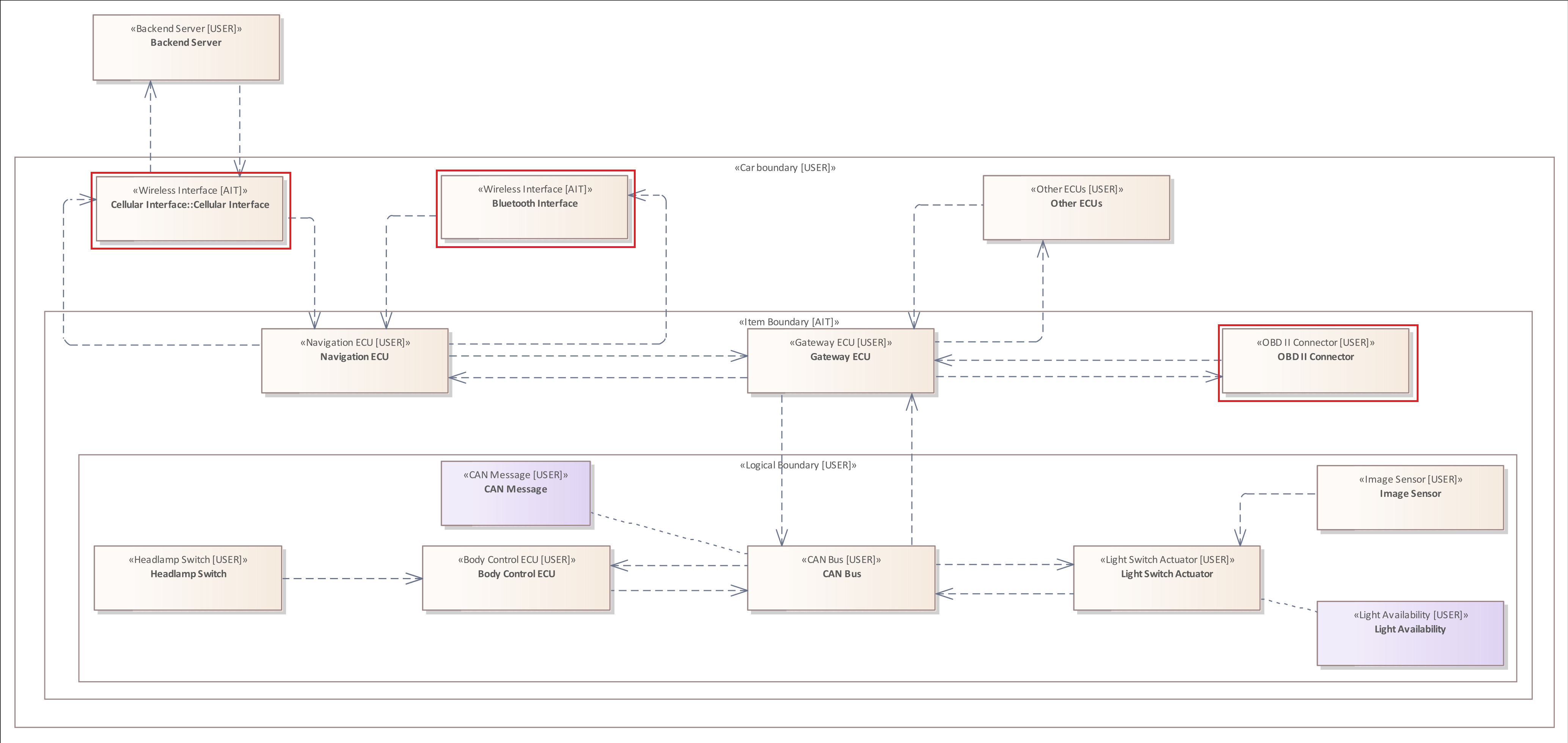
Example 1
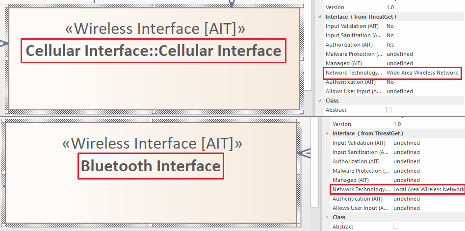
The system model contains two "Wireless Interfaces". However, they differ in the assigned value of the Tagged Value, which is called "Range". This Tagged Value describes the effective range of the respective "Wireless Interface". The "Wireless Interface" called "Cellular Interface" has a larger effective range than the "Bluetooth Interface". Therefore, the "Cellular Interface" has the value "Wide Area Wireless Network" and the "Bluetooth Interface" has the value "Local Area Wireless Network".
The following rule would therefore only return the "Cellular Interface" as analysis result.
Element : "Wireless Interface" {
    "Range" = "Wide Area Wireless Network"
}
Regarding the threat scenario the attack described focuses only on the "Cellular Interface", since the "Bluetooth Interface" has too little "Range" to perform a remote attack.
Example 2
In the previous Example 1, the first variant of the Tagged Value Filter was presented, which checks whether a given Tagged Value has exactly the one defined value. This first variant is to be used only if you know exactly which value would lead to a threat for a diagram component. The second variant is the negated form of the first variant and allows to point out a threat when several values would represent that threat.
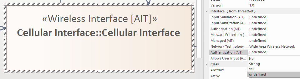
As you can see in the image above, the Tagged Value named "Authentication" has three different values ("No", "Yes", "Undefined") which can be assigned to it. This Tagged Value indicates whether only authenticated connections and data transfers are allowed.
Since users may not always be directly aware of the real value of a Tagged Value, each of them has the default value "Undefined".
The following rule would identify the "Cellular Interface" as a threat even if the Tagged Value "Authentication" is set to "Undefined". The rule from Example 1 would not.
Element : "Wireless Interface" {
    "Authentication" != "Yes"
}
Therefore, you should prefer using this variant over the first one in order to avoid overlooking "Undefined" values.
Example 3
The third variant is used to examine whether the value of a Tagged Value is within a list of values.
The following rule examines whether the value of Tagged Value "Authentication" is set to "No" or "Undefined".
Element : "Wireless Interface" {
    "Authentication" IN ["No", "Undefined"]
}
Compared to the rule from example 2, this rule describes the same threat. The rule in example 2 is only shorter.
Example 4
The fourth variant is the negated form of the third, and is used to examine whether the value of a Tagged Value is not within a list of values.
Consider we would add the value "Strong" to the Tagged Value "Authentication". For example, the value "Strong" would describe that two-factor authentication is required. Furthermore, the value "Yes" would describe that you have to authenticate to send data to this interface.
Element : "Wireless Interface" {
    "Authentication" NOT IN ["Yes", "Strong"]
}
Using this fourth variant, we can describe which values would not be an issue within the system model, as Example 1 would not be enough to define that.
Further Examples
Adding a Tagged Value Filter to a Connector Pattern:
CONNECTOR : "Wireless Flow"{
    SOURCE ELEMENT &
    TARGET ELEMENT &
    "Confidentiality" != "Encrypted"
}
Adding a Tagged Value Filter to a Asset Pattern:
Asset: "CAN Message"{
    "Cybersecurity Attribute" IN ["Integrity", "Confidentiality"]
}
Multiple Filters
In the previous section we showed how the Tagged Value Filter can be used within certain patterns to examine the assigned Tagged Values.
Within the Further Examples we presented the following rule:
CONNECTOR : "Wireless Flow"{
    SOURCE ELEMENT &
    TARGET ELEMENT &
    "Confidentiality" != "Encrypted"
}
This rule consists of a Connector Pattern and three different filters. The mandatory Source Filter and Target Filter and a Tagged Value Filter. All three filters are connected by means of a logical AND (&). Therefore, all three filters must be satisfied for the anti-pattern to be fulfilled.
AND Connected Filters
You can connect as many filters as you wish.
Regarding the threat scenario the attack focuses on a "Cellular Interface" that requires No "Authentication" AND (&) does Not implement an "Input Validation" AND (&) No "Input Sanitization" (No / != Yes) mechanism.
Element : "Wireless Interface" {
    "Range" = "Wide Area Wireless Network" &
    "Authentication" = "No" &
    "Input Validation" = "No" &
    "Input Sanitization" != "Yes"
}
OR Connected Filters
The previous section showed how you can connect multiple filters using a logical AND (&), indicating that all filters have to satisfied. You can also connect multiple filters using a logical OR (|). In this case only one of them has to be satisfied to trigger the threat.
The following rule examines all Connectors of the type "Wireless Flow" that have the Tagged Value "Confidentiality" set to an value unequal to "Encrypted" OR (|) do not provide "Data Safety Integrity" with some form of "Error Correction" or "Checksum".
CONNECTOR : "Wireless Flow"{
    SOURCE ELEMENT &
    TARGET ELEMENT &
    (
        "Confidentiality" != "Encrypted" |
        "Data Safety Integrity" NOT IN ["Error Correction", "Checksum"]
    )
}
The Asset Filter
The Asset Filter is used to examine whether an Element or Connector is linked to a specified Asset.
General Structure:
- HOLDS Asset Pattern
The Asset Filter can be added to the following patterns and filter:
- The Element Pattern
- The Connector Pattern
- The Connector Filter
Example 1
The following rule examines all Elements of the type "Actuator" that are connected to an Asset of the type "Light Availability", with the Tagged Value "Impact Category" equal to "Operational".
ELEMENT : "Actuator" {
    HOLDS Asset: "Light Availability" {
        "Impact Category" = "Operational"
    }
}
Example 2
The previous example shows how you can add an Asset Filter to an Element Pattern.
The following rule examines the system model for a Connector of the type "Wired Flow", that is NOT "Encrypted" and does transport an Asset of the type "CAN Message".
CONNECTOR : "Wired Flow" {
    SOURCE ELEMENT &
    TARGET ELEMET &
    "Confidentiality" != "Encrypted" &
    HOLDS Asset: "CAN Message"
}
The Connector Filter
A Connector Filter is similar to the Connector Pattern, but it is a filter that can be added to an Element Pattern.
Normally the Connector Pattern includes a mandatory Source Filter and Target Filter. However, since it is a filter that is added to a pattern, it only requires one of them. The Element specified within the pattern is the counterpart to the respective Source Element or Target Element.
General Structure:
- HAS CONNECTOR {Source Filter}
- HAS CONNECTOR Type Filter {Source Filter]}
- HAS CONNECTOR {Source Filter ...}
- HAS CONNECTOR Type Filter {Source Filter ...}
- HAS CONNECTOR {Target Filter}
- HAS CONNECTOR Type Filter {Target Filter}
- HAS CONNECTOR {Target Filter ...}
- HAS CONNECTOR Type Filter {Target Filter ...}
The Connector Filter is exclusive for the Element Pattern.
Example 1
The following rule examines all Connectors of the type "Wired Flow", originating from a "High Performance ECU" targeting another "Electronic Control Unit". Additionally, the "Electronic Control Unit" must be updateable.
ELEMENT : "High Performance ECU"{
    HAS CONNECTOR : "Wired Flow"{
        TARGET ELEMENT : "ECU" {
            "Updates" IN ["Yes", "Remote"]
        }
    }
}
Example 2
The following rule highlights the nested concept of the analysis language.
The Connector Pattern examines whether there exists a Connector originating from an Element of the type "Communication ECU" and targeting a "CAN Bus" Element. Furthermore, the Source Element must have an incoming Connector from a "Human Machine Interface" Element.
CONNECTOR {
    SOURCE ELEMENT: "Communication ECU"{
        HAS CONNECTOR {
            SOURCE ELEMENT: "Human Machine Interface"
        }
    } &
    TARGET ELEMENT : "CAN BUS"
}
Example 3
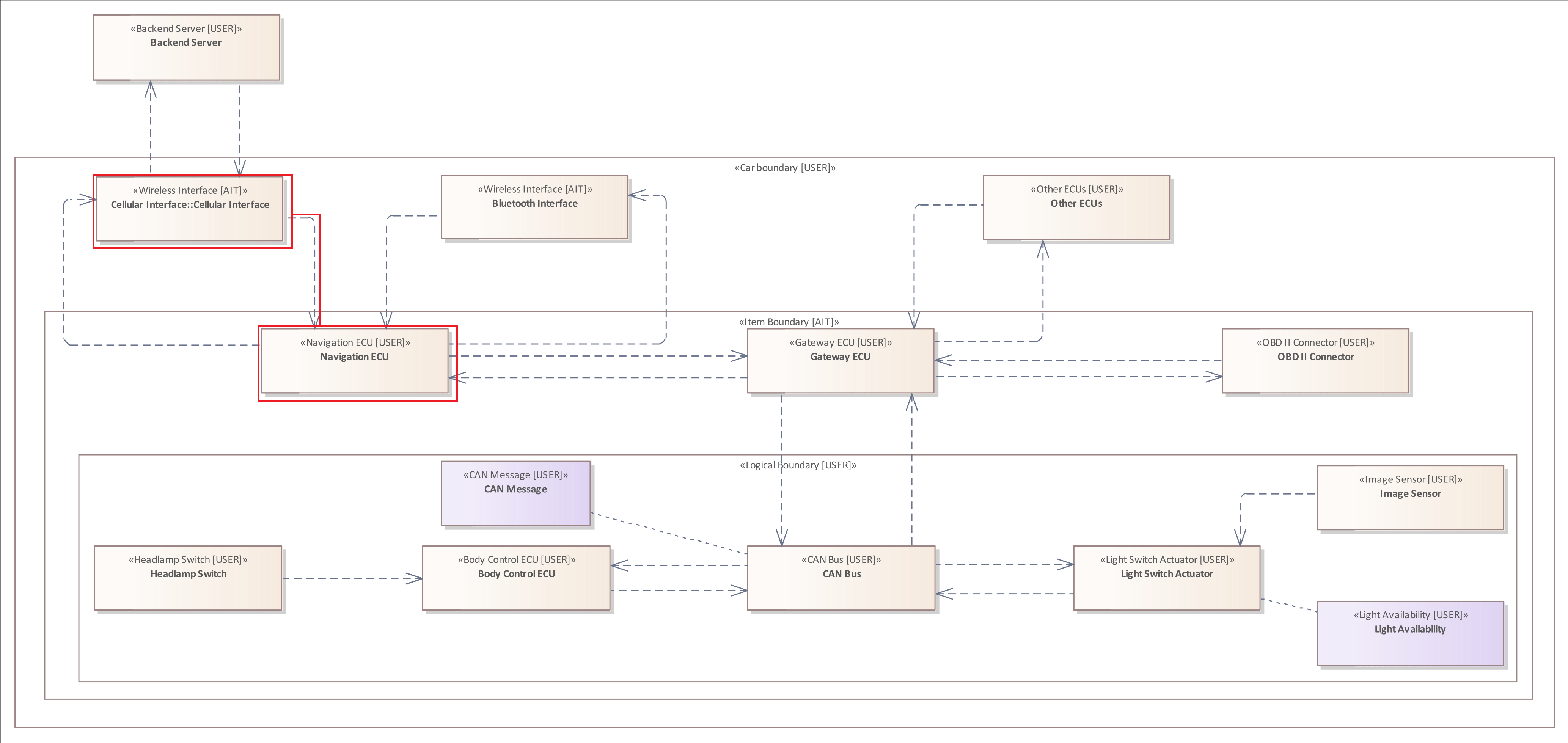
Regarding the threat scenario the attacker must transfer malicious data to the "Communication ECU" labelled "Navigation ECU". Using this control unit the adversary can analyze the internal communication of the vehicle and inject a malicious "CAN Message" to influence it.
The following rule examines whether there exists a Connector originating from the insecure "Cellular Interface" targeting the "Navigation ECU".
Element : "Wireless Interface" {
    "Range" = "Wide Area Wireless Network" &
    "Authentication" != "Yes" &
    "Input Validation" != "Yes" &
    "Input Sanitization" != "Yes" &
    HAS CONNECTOR {
        TARGET ELEMENT : "Communication ECU"
    }
}
The Flow Filter
A Flow Filter is similar to the Flow Pattern, but it is a filter that can be added to an Element Pattern.
Normally the Flow Pattern includes a mandatory Source Filter and Target Filter. However, since it is a filter that is added to a pattern, it only requires one of them. The Element specified within the pattern is the counterpart to the respective Source Element or Target Element.
General Structure:
- HAS FLOW {Source Filter }
- HAS FLOW {Source Filter ...}
- HAS FLOW {Target Filter}
- HAS FLOW {Target Filter ...}
The Flow Filter is exclusive for the Element Pattern.
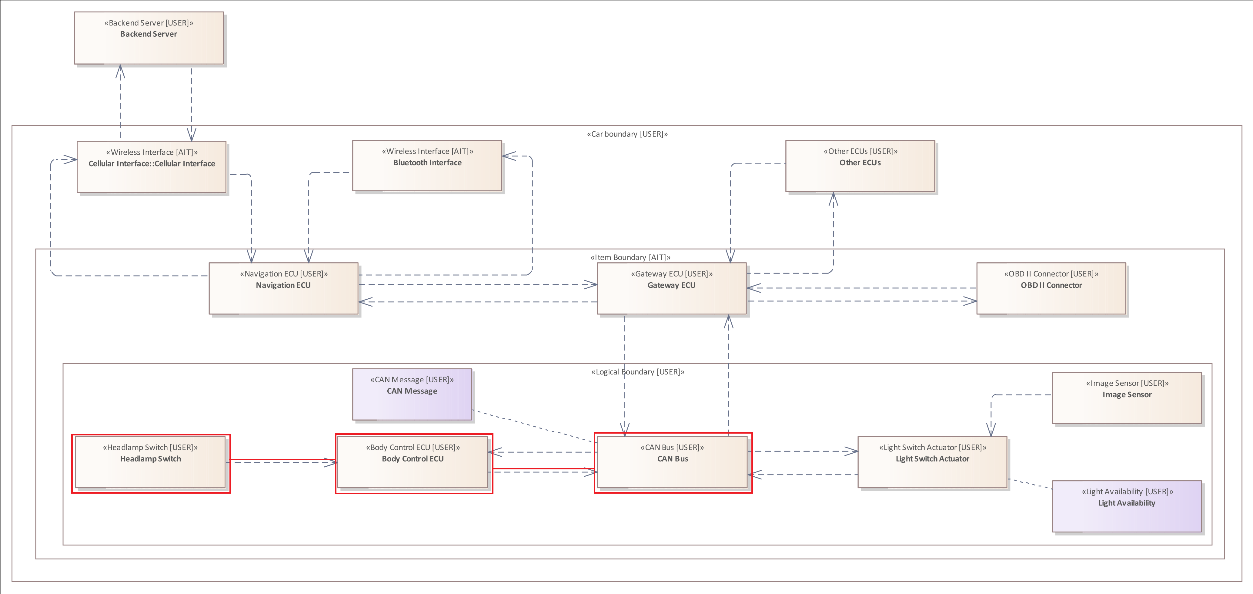
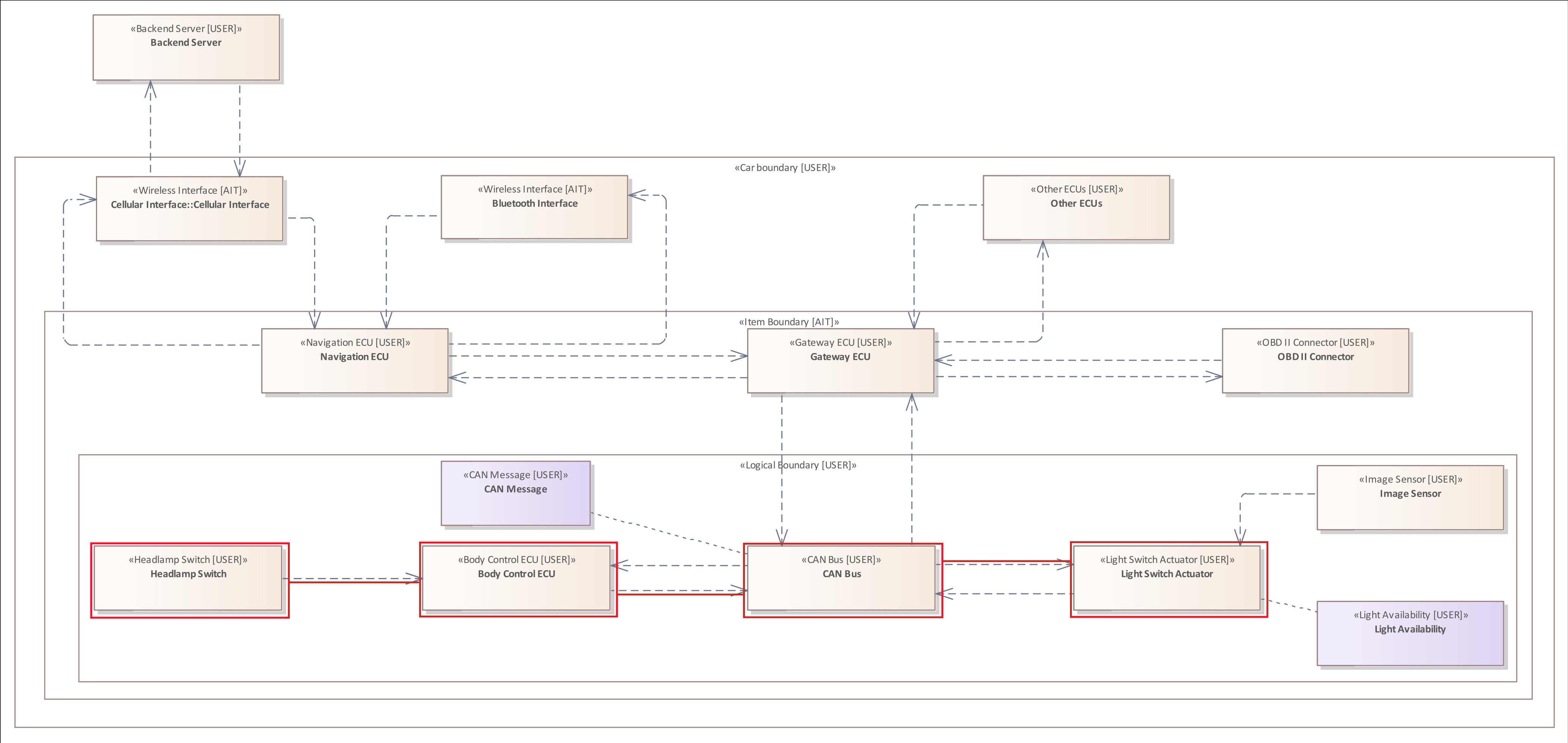
Example 1
The following rule analyzes whether the system model includes an Element of the type "Human Machine Interface" that has an outgoing Flow to an Element of the type "Actuator".
ELEMENT: "Human Machine Interface" {
    HAS FLOW {
        TARGET ELEMENT: "Actuator"
    }
}
The Element Relation Filter
The Element Relation Filter is used to examine the relations of an Element to other Elements or Boundaries.
Due to the structure of the system model, an Element can only contain other Elements but no Boundaries.
The Element Relation Filter does not only examine the direct child and parent relations of an Element or Boundary, but all hierarchical levels.
General Structure:
- CONTAINS Element Pattern
- CONTAINS NO Element Pattern
- CONTAINS ONLY Element Pattern
- CONTAINED BY Element Pattern
- NOT CONTAINED BY Element Pattern
- CONTAINED BY Boundary Pattern
- NOT CONTAINED BY Boundary Pattern
The Element Relation Filter is exclusive for the element Pattern.
Example 1
The following rule examines all Elements that are contained by a Boundary of the type "Logical Boundary".
ELEMENT {
    CONTAINED BY BOUNDARY : "Logical Boundary"
}
Example 2
The following rule examines all Elements that are contained by a Boundary of the type "Item Boundary".
ELEMENT {
    CONTAINED BY BOUNDARY : "Item Boundary"
}
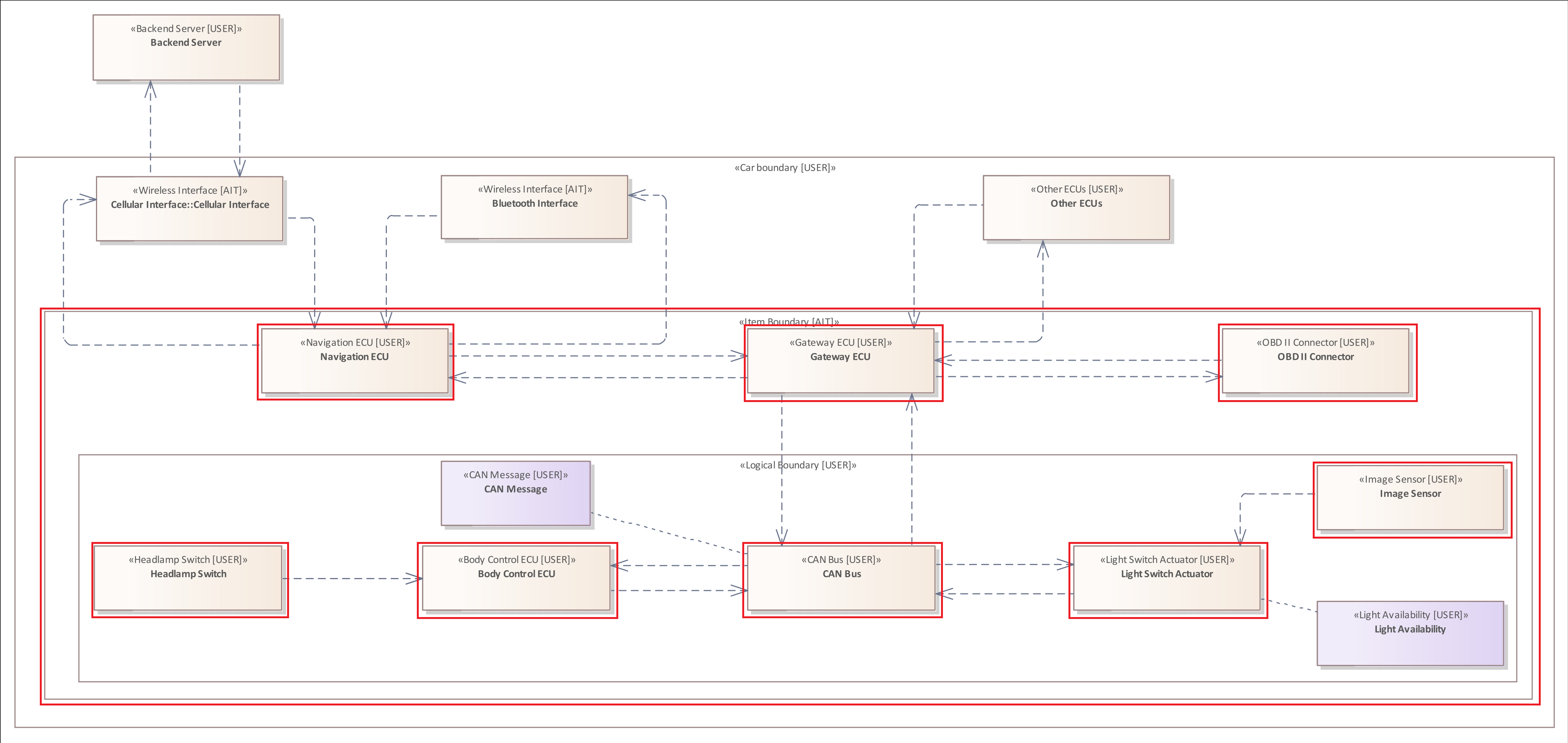
This example shall illustrate the hierchical levels of the Element Relation Filter.
As you can see all Elements contained by the "Logical Boundary" are also contained by the "Item Boundary" and ,therefore, also part of the analysis result.
Example 3
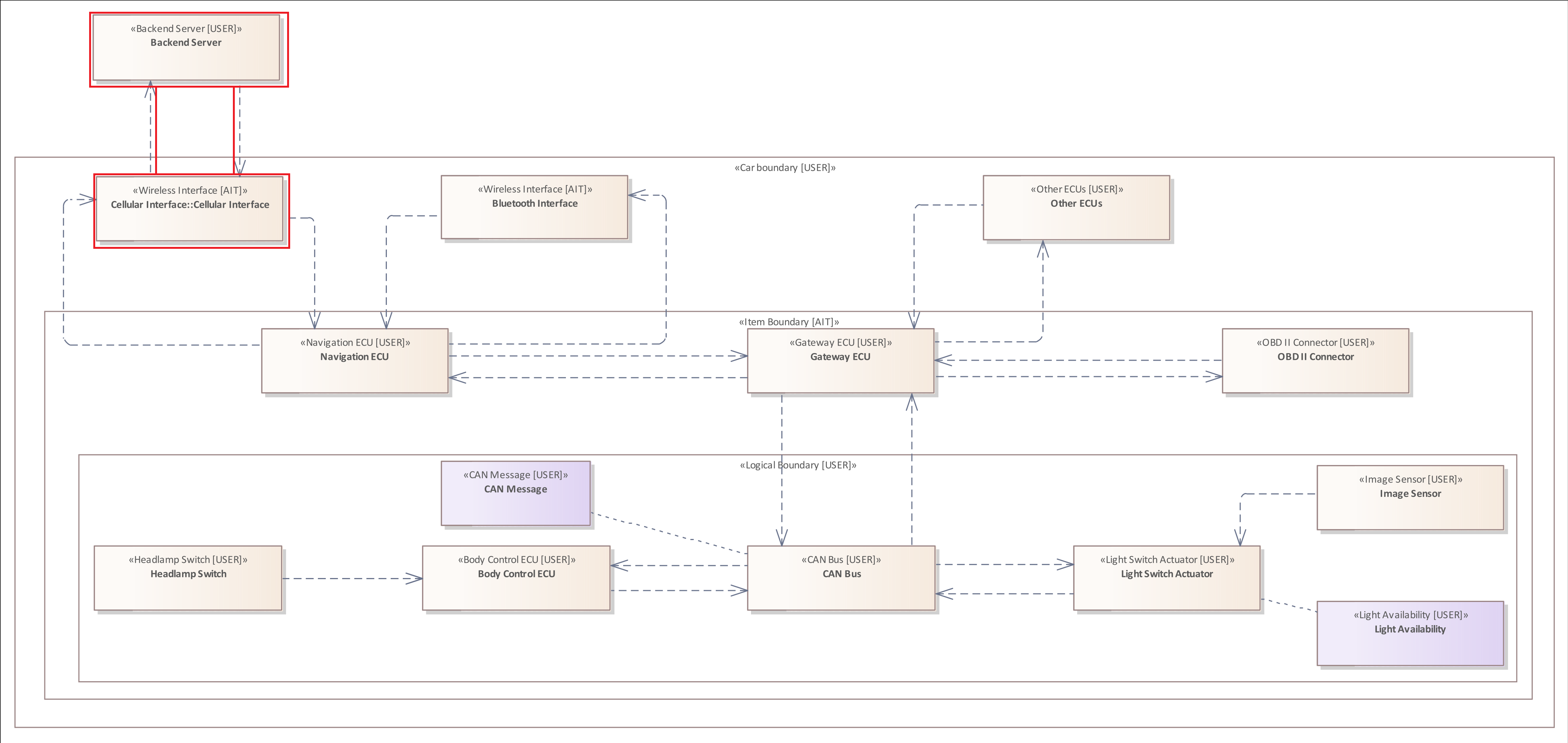
The following rule examines all Elements that are not contained by any Boundary.
ELEMENT {
    NOT CONTAINED BY BOUNDARY
}
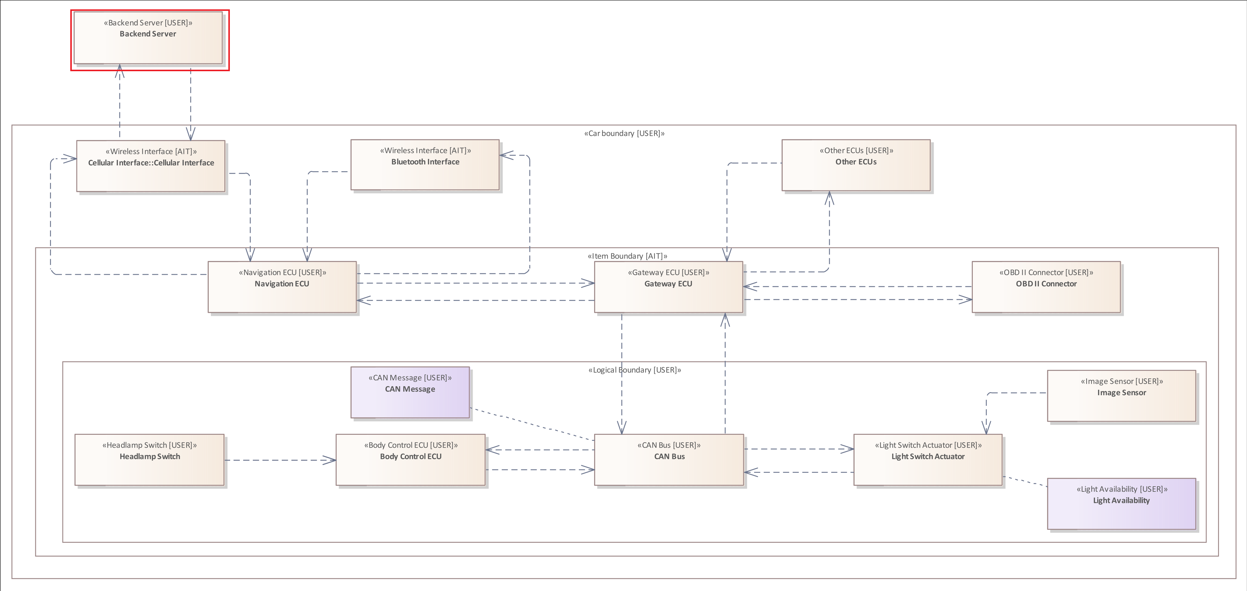
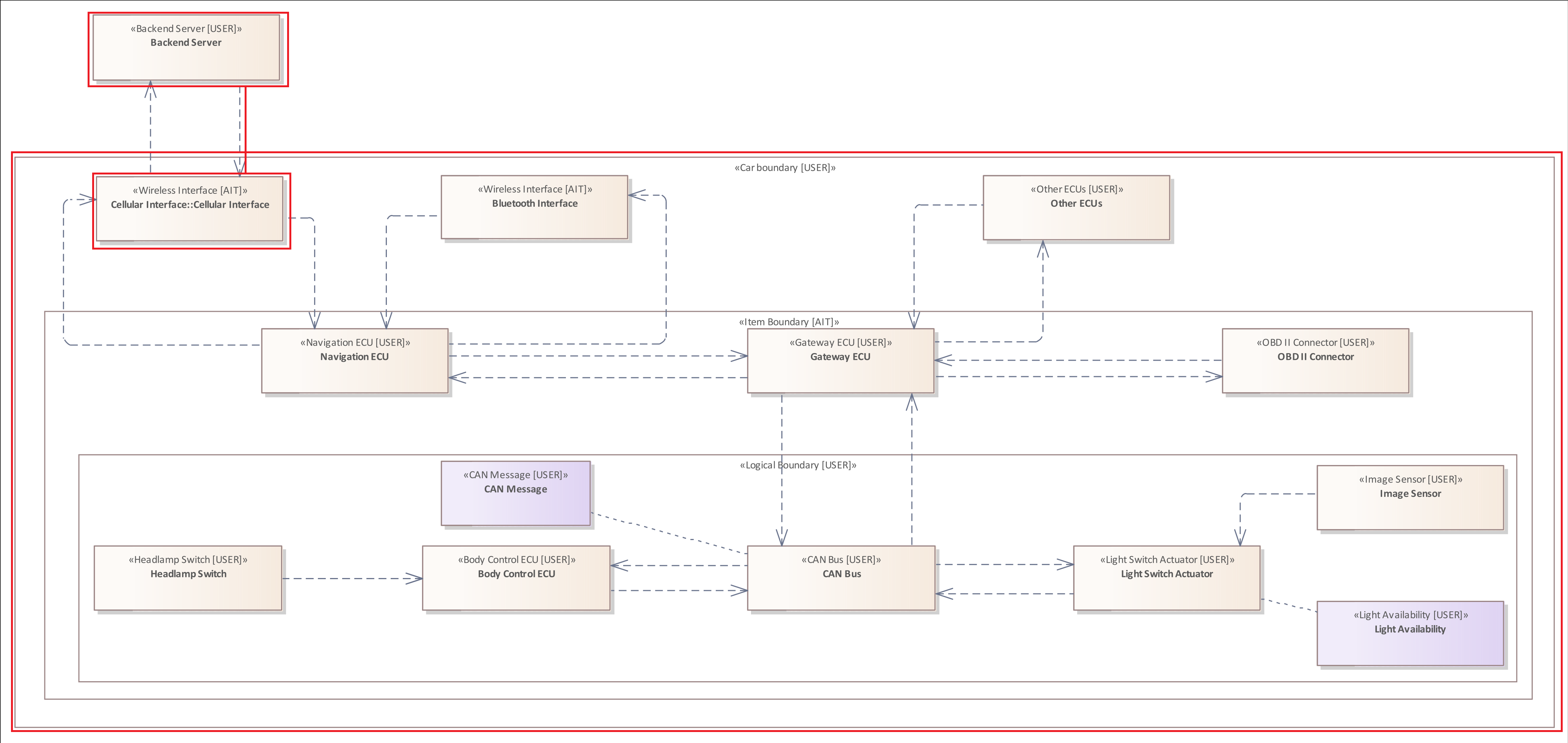
The only Element that is not contained by any Boundary is the "Backend" in the left upper corner of the system model.
Example 4
Regarding the threat scenario the attacker must hack the "Navigation ECU" in order to analyze the internal communication of the vehicle and to inject corrupt "CAN Messages".
If the "Navigation ECU" is updateable from remote but is not contained by "Secure Execution Environment" or has no "Secured Boot" mechanism, the attacker might transfer malicious data to the control unit and force it to reboot in order to compromise it.
ELEMENT : "Communication ECU"{
    "Updates" = "Remote" &
    (
        "Secure Boot" != "Yes" |
        NOT CONTAINED BY BOUNDARY : "Secure Execution Environment"
    )
}
After the "Navigation ECU" has been compromised, the adversary is able to analyze the "CAN Messages" and learn from the provided information.
Further Example
The original system model used in this documentation does not contain an element that is contained in another element. Therefore, the following image shows an adapted version of the system model, which is intended to illustrate that, for example, a "software" is installed on an "Electronic Control Unit", which in turn contains an application. This system model and the following rule is purely for demonstration purposes of this Element Relation Filter.
It checks whether the system model shows that an element of type "Electronic control unit" contains another element of type "Software", which in turn contains an element of type "Application".
ELEMENT : "ECU" {
    CONTAINS ELEMENT : "Software" {
        CONTAINS ELEMENT : "Application"
    }
}
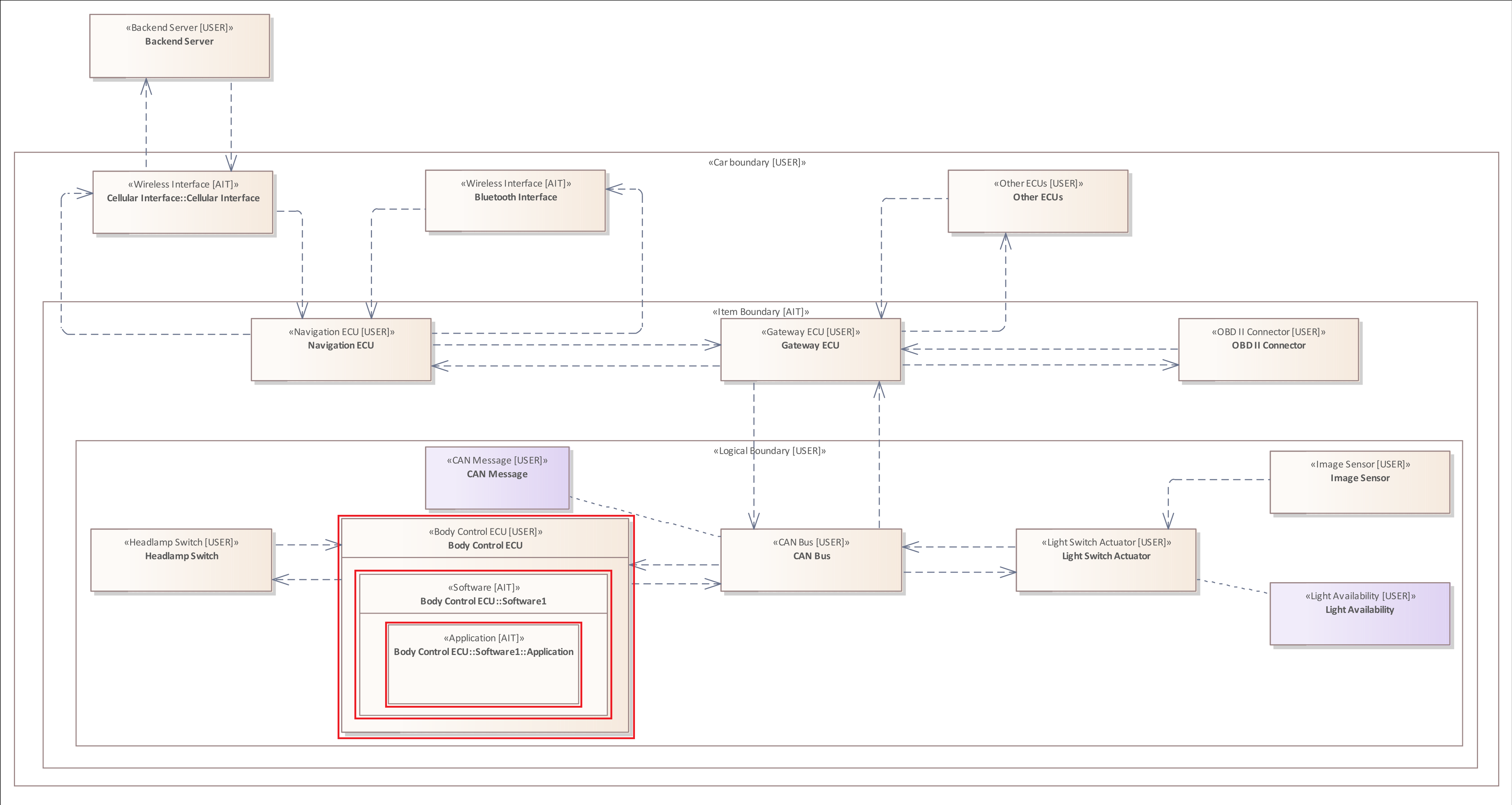
In this extended system model only the "Body Control ECU" contains a "Software" with a running "Application", therefore only this is marked by the rule.
This example is also intended to show how Elements can be modeled together to describe their relationships alongside the Connectors.
This rule is also intended to clarify how relationships between elements can be specified in nested patterns and filters.
The Boundary Relation Filter
The Boundary Relation Filter is used to examine the relations of a Boundary to other Boundaries or Elements.
Due to the structure of the system model, an Element cannot contain a Boundary, but a Boundary can contain Boundaries or Elements.
General Structure:
- CONTAINS Element Pattern
- CONTAINS NO Element Pattern
- CONTAINS ONLY Element Pattern
- CONTAINS Boundary Pattern
- CONTAINS NO Boundary Pattern
- CONTAINS ONLY Boundary Pattern
- CONTAINED BY Boundary Pattern
- NOT CONTAINED BY Boundary Pattern
The Boundary Relation Filter is exclusive for the Boundary Pattern.
Example 1
Generally, the Boundary Relation Filter is almost equal to the Element Relation Filter.
The following rule examines all Boundaries that contain a "Gateway ECU" Element.
Similar to the Element Relation Filter, the Boundary Relation Filter also examines all hierachical levels.
The Crosses Filter
A Crosses Filter can be used to examine whether Connectors and Flows cross an Element or Boundary.
A Connector crosses a Boundary or Element if the Source Element or Target Element are not contained by the same Boundary or Element.
General Structure:
- CROSSES Element Pattern
- CROSSES Boundary Pattern
The Crosses Filter can be added to the following patterns and filters:
- The Connector Pattern
- The Flow Pattern
- The Connector Filter
- The Flow Filter
Example 1
The following rule examines all Connectors of the type "Wireless Flow" that originate from a "Backend" Element and target an "Interface".
CONNECTOR: "Wireless Flow"{
    SOURCE ELEMENT : "Backend" &
    TARGET ELEMENT : "Interface"
    CROSSES BOUNDARY
}
Example 2
Since a Flow can consist of several Connectors and Elements, multiple Connectors of a single Flow can also cross different Boundaries.
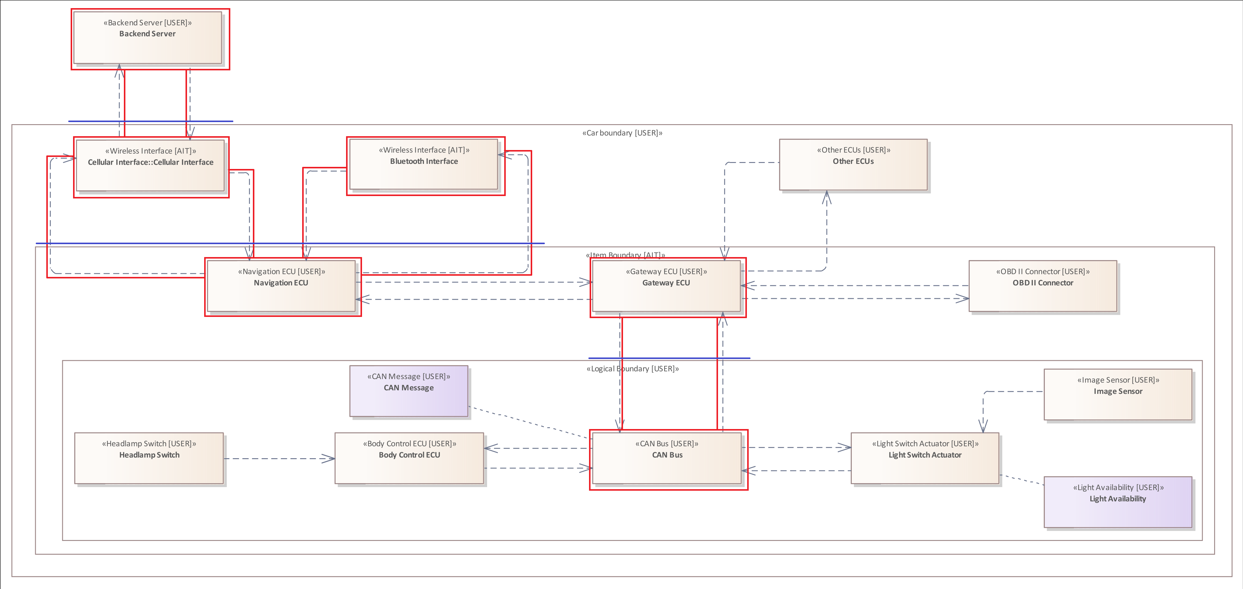
The following rule examines all Connectors within a Flow originating from a "Backend" Element and target an "Actuator".
Flow {
    SOURCE ELEMENT : "Backend" &
    TARGET ELEMENT : "Actuator"
    CROSSES BOUNDARY
}
Further Examples
The following rule illustrates the usage of the Crosses Filter in a Connector Filter. It is the same rule
ELEMENT {
    HAS CONNECTOR {
        TARGET ELEMENT &
        CROSSES BOUNDARY
    }
}
Since the rule contains no type-filters, all connectors that cross a Boundary are marked.
The following rule illustrates the usage of the Crosses Filter in a Flow Filter.
ELEMENT : "Communication ECU" {
    HAS FLOW {
        TARGET ELEMENT : "Actuator"&
        CROSSES BOUNDARY : "Logical Boundary"
    }
}
The Includes Filter
As described within the section of the Flow Pattern it is neither possible to add a type filter to the pattern nor can you add a Tagged Value Filter. This is due to the fact that a Flow consists of multiple Elements and Connectors.
However, it is possible to examine the Elements and Connectors within a Flow using the Includes Filter.
General Structure:
- INCLUDES Element Pattern
- INCLUDES NO Element Pattern
- INCLUDES ONLY Element Pattern
- INCLUDES Connector Pattern
- INCLUDES NO Connector Pattern
- INCLUDES ONLY Connector Pattern
This filter is exclusive for:
- The Flow Pattern
- The Flow Filter
Example 1
The following rule examines whether the system model contains a Flow originating from a "Wireless Interface" with the Tagged Value "Range" set to "Wide Area Wireless Network", targeting an "Actuator", that includes an Element of the type "High Performance ECU", which in turn does NOT provide a "Forward Restriction" mechnism. A forward restriction mechanism checks the incoming "CAN Messages" and examines their content. This mechanism would prevent an attack targeting the CAN Message system of the vehicle.
FLOW {
    SOURCE ELEMENT: "Wireless Interface" {
        "Range" = "Wide Area Wireless Network"
    }&
    TARGET ELEMENT: "Actuator" &
    INCLUDES ELEMENT: "High Performance ECU"{
        "Forward Restriction" != "Yes"
    }
}
The only "High Performance ECU" within the system model is the "Gateway ECU" Element which is part of the Flow from the "Cellular Interface" to the "Light Switch Actuator".
Example 2
The previous example showed how the Includes Filter can be used to examine whether a Flow includes at least one Element that satisfies the Element Pattern.
The following rule shows how the Includes Filter can be used to examine whether NONE of the Elements included in the Flow provides a "Forward Restriction" mechnism.
FLOW {
    SOURCE ELEMENT: "Wireless Interface" {
        "Range" = "Wide Area Wireless Network"
    }&
    TARGET ELEMENT: "Actuator" &
    INCLUDES NO ELEMENT{
        "Forward Restriction" = "Yes"
    }
}
Please notice the last Tagged Value Filter "Forward Restriction" = "Yes". Compared to Example 1 it is "Forward Restriction" EQUALS "Yes".
This is because in the other usage it would be double negation and thus miss the purpose.
Example 3
In order to avoid the double negation you can use the third variant of the Includes Filter.
The following rule is the rule reformulated form of the Example 2.
FLOW {
    SOURCE ELEMENT: "Wireless Interface" {
        "Range" = "Wide Area Wireless Network"
    }&
    TARGET ELEMENT: "Actuator" &
    INCLUDES ONLY ELEMENT{
        "Forward Restriction" != "Yes"
    }
}
Please notice again the last Tagged Value Filter "Forward Restriction" != "Yes". Compared to Example 2 it is "Forward Restriction" UNEQUALS "Yes".
With these examples we want to help you avoiding issues thinking in double negations. Therefore, we recommend using this rule from Example 3.
Example 4
The previous three examples showed how you can use the Includes Filter within a Flow Pattern to analyze the Elements contained by a Flow.
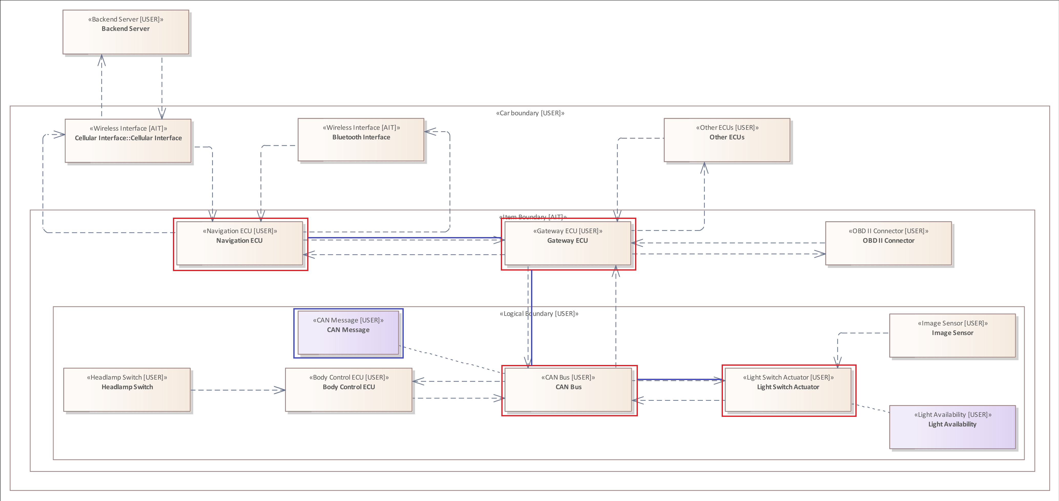
The following rule is similar to Example 1. It shows how to use Includes Filter in order to examine whether a Flow includes a specified Connector. In this case, it is specified that the Flow must contain a Connector originating from a "High Performance ECU" and must target an Element of the type "CAN Bus".
FLOW {
    SOURCE ELEMENT: "Wireless Interface" {
        "Range" = "Wide Area Wireless Network"
    }&
    TARGET ELEMENT: "Actuator" &
    INCLUDES CONNECTOR{
        SOURCE ELEMENT: "High Performance ECU" &
        TARGET ELEMENT: "CAN Bus"
    }
}
The specified connector is highlighted in blue.
Example 5
The previous example showed how the Includes Filter can be used to examine a Flow for a single Connector.
The following rule examines all Connectors contained by the Flow whether they are linked to an Asset of the type "CAN Message".
FLOW {
    SOURCE ELEMENT: "Communication ECU" {
        "Range" = "Wide Area Wireless Network"
    }&
    TARGET ELEMENT: "Actuator" &
    INCLUDES ONLY CONNECTOR{
        SOURCE ELEMENT &
        TARGET ELEMENT &
        HOLDS ASSET: "CAN Message"
    }
}
Please note that the Source Filter and Target Filter within the Includes Filter is mandatory if you want to examine a Connector.
Using the concept of Assets you can examine the movement of data within the system.
Example 6
Regarding the threat scenario we have presented now all patterns and filters that are necessary to describe the final attack.
The attacker sends a corrupt "CAN Message" via the manipulated "Navigation ECU" which is forwarded by the internal communication system of the vehicle to the "Light Switch Actuator" because none of the Elements within the path implements a "Forward Restriction" mechanism.
FLOW {
    SOURCE ELEMENT: "Communication ECU" {
        "Range" = "Wide Area Wireless Network"
    }&
    TARGET ELEMENT: "Actuator" &
    INCLUDES ONLY ELEMENT {
        "Forward Restriction" != "Yes"
    }&
    INCLUDES ONLY CONNECTOR{
        SOURCE ELEMENT &
        TARGET ELEMENT &
        HOLDS ASSET: "CAN Message"
    }
}
To express this process, we use two Includes filters. The first one checks if the Flow contains only Elements which have no "Foward Restriction" and the second one checks if each Connector within the Flow transports an Asset of the type "CAN Message".
The Requires and Provides Filters
To be able to define a continuous propagation through the threat analysis, pre- and postconditions are required. Those can be defined in the webinterface as Capabilities.
To model a precondition, the Requires Filter is used. For a postcondition, the Provides Filter.
General structure for the Requires Filter:
- REQUIRES CAPABILITY capability >= value
- REQUIRES ATTACKER CAPABILITY capability >= value
General structure for the Provides Filter:
- PROVIDES CAPABILITY capability := value
- PROVIDES ATTACKER CAPABILITY capability := value
REQUIRES|PROVIDES CAPABILITY is used for local pre-/postconditions, whereas REQUIRES|PROVIDES ATTACKER CAPABILITY is used for global ones.
Example 1
In this example, an attacker is able to read from the data store. Furthermore, the data store does not support a secure boot, hence cannot detect if any changes in the configuration file have been made. This can lead to the attacker changing it to allow them to modify the data.
ELEMENT : "Data Store" {
    REQUIRES CAPABILITY "Read" >= "true" &
    "Secure Boot" != "yes" &
    PROVIDES CAPABILITY "Modify" := "true"
}
In the Requires Filter, the >= checks the order in which the values in the capabiity are put. In Read, the value true has the highest position, therefore it will only trigger if there is read access to the data store.
The Provides Filter makes sure, that after the attack has been finished the attacker is able to modify the data, and has therefore been set to true.
Full Syntax Description
This section contains a description of the entire syntax of the THREATGET analysis language.
The language consists of a set of production rules. Each rule describes how a non-terminal symbol can be "replaced" or "extended" by a string consisting of non-terminal symbols and terminal symbols.
In addition, it should be explained that a terminal symbol is a fixed part of the language syntax. In contrast, a non-terminal symbol must be replaced by its corresponding production rule.
The following table lists all production rules of the language.
On the left side are the non-terminal symbols, and on the right side the respective symbols to replace the non-terminal ones.
A non-terminal symbol can have several alternatives by which it can be replaced. Each of them is displayed in a separate line.
Expressions in THREATGET come with different quantifiers. They imply how often a specific expression can occur within a rule. Below you can find the list of quantifiers.
(...)?      -> zero or one time
(...)*      -> zero, one or multiple times
(...)+      -> one or multiple times
(...|...)   -> logical OR                       Parentheses are mandatory part of the Syntax
...&...     -> logical AND
query                       ->  query (& query)+
                                query (| query)+
                                pattern

pattern                     ->  element_pattern
                                boundary_pattern
                                connector_pattern
                                flow_pattern

element_pattern             ->  (element_pattern (| element_pattern)+)
                                ELEMENT (type_filter)? ({element_filters})?

asset_pattern               ->  (asset_pattern (| asset_pattern)+)
                                ASSET (type_filter)? ({asset_filters})?

boundary_pattern            ->  (boundary_pattern (| boundary_pattern)+)
                                BOUNDARY (type_filter)? ({boundary_filters})?

connector_pattern           ->  (connector_pattern (| connector_pattern)+)
                                CONNECTOR (type_filter)? {source_filter & target_filter (& connector_filters)}

flow_pattern                ->  (flow_pattern (| flow_pattern)+)
                                FLOW {source_filter & target_filter (& flow_filters)}

source_filter               ->  SOURCE element_pattern

target_filter               ->  TARGET element_pattern

element_filters             ->  element_filters (& element_filters)+
                                ( element_filters (| element_filters)+ )
                                tagged_value_filter
                                asset_filter
                                element_relation_filter
                                connector_filter
                                flow_filter

asset_filters               ->  asset_filters (& asset_filters)+
                                ( asset_filters (| asset_filters)+ )
                                tagged_value_filter
                                impact_filter

boundary_filters            ->  boundary_filters (& boundary_filters)+
                                ( boundary_filters (| boundary_filters)+ )
                                boundary_relation_filter

connector_filters           ->  connector_filters (& connector_filters)+
                                ( connector_filters (| connector_filters)+ )
                                tagged_value_filter
                                crosses_filter
                                asset_filter


flow_filters                ->  flow_filters (& flow_filters)+
                                ( flow_filters (| flow_filters)+ )
                                crosses_filter
                                flow_includes_filter

type_filter                 ->  : "type"
                                : != "type"
                                : IN ["type" (, "type")*]
                                : NOT IN ["type" (, "type")*]

tagged_value_filter         ->  "key" = "value"
                                "key" != "value"
                                "key" IN ["value" (, "value")*]
                                "key" NOT IN ["value" (, "value")*]

asset_filter                ->  HOLDS asset_pattern
                                HOLDS NO asset_pattern

element_relation_filter     ->  CONTAINS element_pattern
                                CONTAINS NO element_pattern
                                CONTAINS ONLY element_pattern
                                CONTAINED BY element_pattern
                                CONTAINED BY boundary_pattern
                                NOT CONTAINED BY element_pattern
                                NOT CONTAINED BY boundary_pattern
                                CONTAINED BY ONLY element_pattern
                                CONTAINED BY ONLY boundary_pattern

connector_filter            ->  HAS CONNECTOR (type_filter)? { source_filter (& connector_filters)? }
                                HAS NO CONNECTOR (type_filter)? { source_filter (& connector_filters)? }
                                HAS CONNECTOR (type_filter)? { target_filter (& connector_filters)? }
                                HAS NO CONNECTOR (type_filter)? { target_filter (& connector_filters)? }

flow_filter                 ->  HAS FLOW { source_filter (& flow_filters)? }
                                HAS NO FLOW { source_filter (& flow_filters)? }
                                HAS FLOW { target_filter (& flow_filters)? }
                                HAS NO FLOW { target_filter (& flow_filters)? }

boundary_relation_filter    ->  CONTAINS element_pattern
                                CONTAINS boundary_pattern
                                CONTAINS NO element_pattern
                                CONTAINS NO boundary_pattern
                                CONTAINS ONLY element_pattern
                                CONTAINS ONLY boundary_pattern
                                CONTAINED BY boundary_pattern
                                NOT CONTAINED BY boundary_pattern
                                CONTAINED BY ONLY boundary_pattern

crosses_filter              ->  CROSSES element_pattern
                                CROSSES boundary_pattern

flow_includes_filter        ->  INCLUDES element_pattern
                                INCLUDES NO element_pattern
                                INCLUDES ONLY element_pattern
                                INCLUDES connector_pattern
                                INCLUDES NO connector_pattern
                                INCLUDES ONLY connector_pattern